24
Board Interfaces
4.4
Connector Pin Assignments
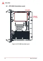
See “cPCI-6520 Board Layout” on page 21 for connector locations.
Front Panel Connectors
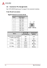
Gigabit Ethernet Connectors (RJ-45)
Pin #
GbE Signal
1
2
LAN_TX0-
3
4
5
LAN_TX2-
6
LAN_TX1-
7
8
Status
Speed LED
(Green/Amber)
Activity LED
(Amber)
Network link is not established
or system powered off
OFF
OFF
10 Mbps
Link
OFF
ON
Active
OFF
Blinking
100 Mbps
Link
Green
ON
Active
Green
Blinking
1000 Mbps
Link
Amber
ON
Active
Amber
Blinking
8
1
Speed
Activity
Summary of Contents for cPCI-6520
Page 8: ...viii List of Figures This page intentionally left blank ...
Page 10: ...x List of Tables This page intentionally left blank ...
Page 18: ...8 Introduction This page intentionally left blank ...
Page 30: ...20 Functional Description This page intentionally left blank ...
Page 52: ...42 Board Interfaces This page intentionally left blank ...
Page 65: ...Getting Started 55 cPCI 6520 5 5 Secure the CFast adapter with two screws as shown below ...
Page 66: ...56 Getting Started This page intentionally left blank ...
Page 74: ...64 Utilities This page intentionally left blank ...

