12
Installation
2.3 Input Signal Jumper Setting
Note
:
This section is for PCI-7250 and PCI-7251 only.
There are 8 jumpers (JP1 to JP8) on the PCI-7250 and PCI-7251;
each associated with one digital input to configure that channel as
either AC-Filtered or Non-AC-Filtered. Digital input channels and
corresponding jumpers are listed in the table below
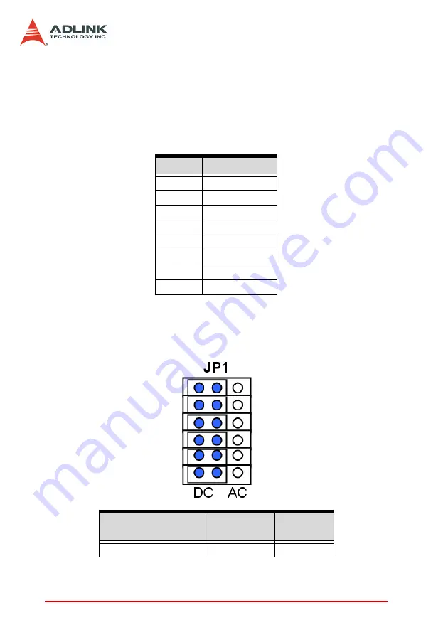
The default setting for the input signal selection is Non-AC-Filter
(DC signal input), which is shown as below:
JP1
JUMPER INPUT SIGNAL
JP1
DI0
JP2
DI1
JP3
DI2
JP4
DI3
JP5
DI4
JP6
DI5
JP7
DI6
JP8
DI7
Table 2-1: Jumpers and DI Channels
Input Signal Selection
Non-AC-Filter
(DC Signal)
AC-Filter
(AC Signal)
Jumper JP1 - JP8
2-3
1-2
Table 2-2: Input Signal Selection Jumper Settings
Summary of Contents for cPCI-7252
Page 4: ......
Page 10: ......
Page 18: ...8 Introduction ...
Page 20: ...10 Installation 2 2 PCB Layout PCI 7250 PCB Layout Figure 2 1 PCI 7250 Layout ...
Page 21: ...Installation 11 cPCI 7252 PCB Layout Figure 2 2 cPCI 7252 Layout ...
Page 28: ...18 Installation ...
Page 32: ...22 Registers ...
Page 43: ...C C Libraries 33 Return Code ERR_NoError ERR_BoardNoInit ...
Page 48: ...38 C C Libraries ...
Page 52: ...42 Appendix ...


