Hardware Reference
33
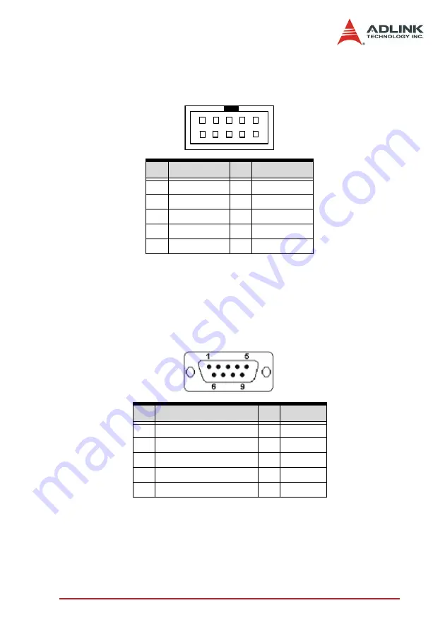
GPIO 0
Pins IN0 and OUT0 are used by channel 0
Pins IN1 and OUT1 are used by channel 1
GPIO 1
Pins IN2 and OUT2 are for channel 2
Pins IN3 and OUT3 are for channel 3
PIN
Function
PIN
Function
1
GND
2
CH4 video in
3
CH5 video in
4
GND
5
GND
6
CH6 video in
7
CH7 video in
8
GND
9
GND
10
GND
Table 2-27: Channel Extension Video Input (CN8)
PIN
Function
PIN Function
1
IN0 (External interrupt)
6
GND
2
OUT0
7
GND
3
IN1 (External interrupt)
8
GND
4
OUT1
9
+5V
5
GND
Table 2-28: GPIO 0 Pinout
10
9
2
1
Summary of Contents for cRTV-24
Page 4: ......
Page 8: ...List of Tables iv Table 5 2 C C Data Types 83 Table 5 3 Pixel Data 122 ...
Page 10: ......
Page 18: ...8 Introduction ...
Page 34: ...24 Hardware Reference Figure 2 8 STRG Address Jumpers ...
Page 55: ...Installation Guide 45 Figure 3 2 cRTV 24 3U cPCI ...
Page 61: ...Installation Guide 51 ...
Page 62: ...52 Installation Guide ...
Page 64: ...54 Installation Guide The Device Manager should be as follows ...
Page 67: ...Installation Guide 57 ...
Page 68: ...58 Installation Guide 3 When the following window appears please click Con tinue Anyway ...
Page 70: ...60 Installation Guide The Device Manager should be as follows ...
Page 72: ...62 Installation Guide 3 Click the Finish button to finish the installation ...
Page 76: ...66 Installation Guide ...
Page 144: ...134 Function Library ...
Page 174: ...164 Programming Guide ...


