Overview
3
CT-61
1.3
Block Diagram
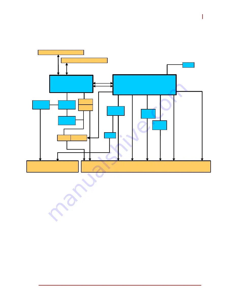
Figure 1-1: CT-61 Block Diagram
Intel
®
Core™i7
DMI
J1/J2
J3/J4/J5
Pericom
PI7C9X13
PCIe x8
PCIe x4
PCIe x4
Pericom
PI7C9X13
PMC 2
PCIe x8
PCI-X 64b/133M
TMDSB
Intel
82574L
Intel
82574L
PCIe x1
PCIe x1
GbE3
GbE4
6x USB
3x SATA
HDA
5x GPIO
RTC
PCIe x4
LVDS
SIO
ITE8783
LPC
KB/MS
2x COM
COM4
BMC
2.5” HDD
SATA1
BIOS
SPI
QM57 PCH
XMC
Soldered w/ ECC, max. 4GB
Soldered w/ ECC, max. 4GB
DDR3 800/1066
PCIe
Switch
PMC 1
Rear I/O
Rear I/O
PCI 64b/66M
IPMB 0/1
RGB
Summary of Contents for CT-61
Page 8: ...viii List of Tables This page intentionally left blank ...
Page 10: ...x List of Figures This page intentionally left blank ...
Page 20: ...10 Specifications This page intentionally left blank ...
Page 38: ...28 Board Interfaces This page intentionally left blank ...
Page 42: ...32 Driver Installation This page intentionally left blank ...
Page 52: ...42 Utilities This page intentionally left blank ...
Page 64: ...54 BIOS Setup Utility PC Health Configuration ...
Page 74: ...64 BIOS Setup Utility This page intentionally left blank ...


