Introduction
21
DEX-100
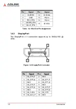
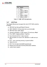
Table 1-14: DVI Port Pin Assignments
1.7
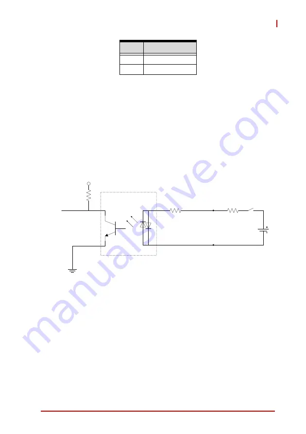
DI/O Sample Circuits
1.7.1
Isolated Digital Input Circuits
The input can accept voltages up to 24V, with extra 10k
Ω
input
resistors (Rs). Connections between outside signals are as fol-
lows.
Figure 1-20: Digital Input Sample Application Circuit
2
GND(CHGND)
3
V- (DGND)
Pin
Signal
3.3V
2.4k
ȍ
IDI_H
IDI_L
Opto-
isolators
Rs
IDI
Summary of Contents for DEX-100
Page 7: ...Table of Contents vii DEX 100 Getting Service 69...
Page 8: ...viii Table of Contents Leading EDGE COMPUTING...
Page 10: ...x List of Tables Leading EDGE COMPUTING This page intentionally left blank...
Page 12: ...xii List of Figures Leading EDGE COMPUTING This page intentionally left blank...
Page 18: ...6 Introduction Leading EDGE COMPUTING Figure 1 2 Top View Figure 1 3 Right Side View 140...
Page 19: ...Introduction 7 DEX 100 Figure 1 4 Left Side View Figure 1 5 Rear Side View...
Page 34: ...22 Introduction Leading EDGE COMPUTING This page intentionally left blank...
Page 39: ...Getting Started 27 DEX 100...
Page 42: ...30 Getting Started Leading EDGE COMPUTING This page intentionally left blank...
Page 63: ...BIOS Setup 51 DEX 100 SEMA Features Shows features supported by the SEMA version...
Page 66: ...54 BIOS Setup Leading EDGE COMPUTING Flags Shows BMC flags with exception codes...
Page 67: ...BIOS Setup 55 DEX 100 Power Up Lists Power Up Watchdog status...
Page 76: ...64 BIOS Setup Leading EDGE COMPUTING This page intentionally left blank...
Page 80: ...68 Important Safety Instructions Leading EDGE COMPUTING This page intentionally left blank...


