


BIOS Setup
125
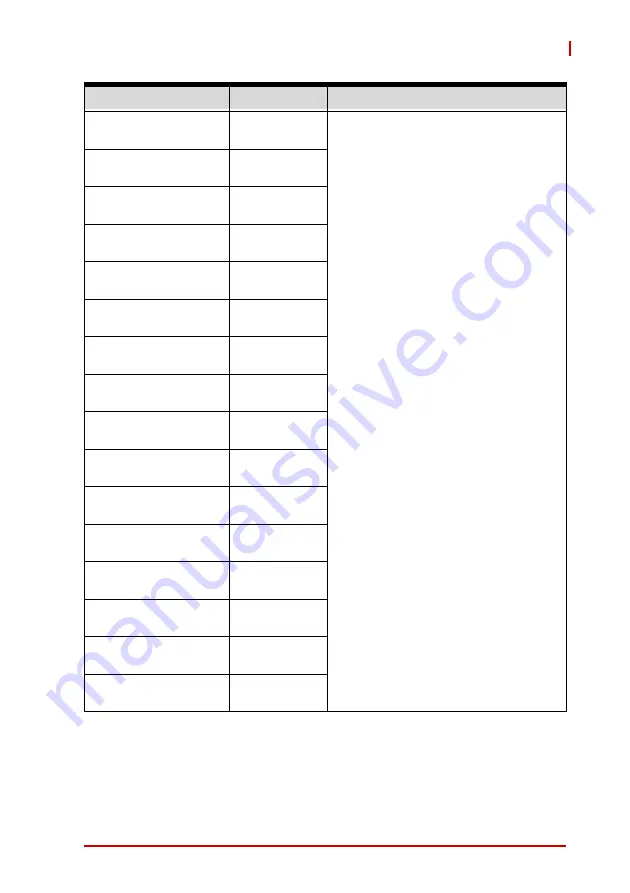
DLAP-3200-CF
U3_USB1_TX_P
(EXTERNAL USB)
Disabled
Enabled
Enables/Disables this USB Physical
Connector (physical port). Once
disabled, any USB devices plugged
into the connector will not be detected
by BIOS or OS.
U3_USB2_TX_P
(EXTERNAL USB)
Disabled
Enabled
U3_USB3_TX_P
(EXTERNAL USB)
Disabled
Enabled
U3_USB4_TX_P
(EXTERNAL USB)
Disabled
Enabled
U3_USB5_TX_P (PIN
HEADER USB)
Disabled
Enabled
U3_USB6_TX_P (PIN
HEADER USB)
Disabled
Enabled
U2_USB1_P
(EXTRENAL USB)
Disabled
Enabled
U2_USB2_P
(EXTRENAL USB)
Disabled
Enabled
U2_USB3_P
(EXTRENAL USB)
Disabled
Enabled
U2_USB4_P
(EXTRENAL USB)
Disabled
Enabled
U2_USB5_P (PIN
HEADER USB)
Disabled
Enabled
U2_USB6_P (PIN
HEADER USB)
Disabled
Enabled
U2_USB7_P (M.2
Key_B)
Disabled
Enabled
U2_USB8_P (M.2
Key_E)
Disabled
Enabled
U2_USB9_P
(INTERNAL USB)
Disabled
Enabled
U2_USB14_P
(INTERNAL USB)
Disabled
Enabled
Feature
Options
Description
Summary of Contents for DLAP-3200-CF Series
Page 8: ...viii List of Tables This page intentionally left blank ...
Page 10: ...x List of Figures This page intentionally left blank ...
Page 14: ...4 Introduction This page intentionally left blank ...
Page 21: ...Specifications 11 DLAP 3200 CF Figure 2 3 DLAP 3200 CF Left Side View 194 50 182 00 ...
Page 22: ...12 Specifications Figure 2 4 DLAP 3200 CF Right Side View 194 50 182 00 ...
Page 23: ...Specifications 13 DLAP 3200 CF Figure 2 5 DLAP 3200 CF Rear View 235 00 ...
Page 26: ...16 System Layout Figure 3 2 DLAP 3200 CF Rear Panel I O P N O ...
Page 54: ...44 System Layout This page intentionally left blank ...
Page 59: ...Getting Started 49 DLAP 3200 CF Left side screws ...
Page 60: ...50 Getting Started Right side screws ...
Page 62: ...52 Getting Started 3 Remove the 4 screws attaching the left drive bay to the chassis ...
Page 69: ...Getting Started 59 DLAP 3200 CF Right side screws ...
Page 70: ...60 Getting Started Left side screws ...
Page 71: ...Getting Started 61 DLAP 3200 CF Bottom screws ...
Page 85: ...Getting Started 75 DLAP 3200 CF 3 Remove the 8 screws attaching the BM cover to the chassis ...
Page 86: ...76 Getting Started 4 Remove the BM cover ...
Page 87: ...Getting Started 77 DLAP 3200 CF 5 Remove the fan ...
Page 94: ...84 Getting Started This page intentionally left blank ...
Page 140: ...130 BIOS Setup This page intentionally left blank ...
Page 150: ...140 Consignes de Sécurité Importante This page intentionally left blank ...


