22
Getting Started
3.5
Mounting
The DMI-1040 can be panel mounted using 4 countersunk M5
screws and O-rings. Make sure there is adequate space behind
the panel for ventilation and I/O connectors, and that the panel
material and thickness can support the weight of the device.
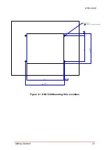
1. Prepare the panel opening and screw holes as shown in
the Figure 3-1 below (M5 thread or
Φ
5.5 through hole).
2. Attach I/O cables to the device before installing into the
panel if rear access will be limited after installation (see
“Mechanical Layout” on page 6.).
3. Place the device into the panel cutout and secure with 4
countersunk M5xL40 screws and O-rings provided as
shown in Figure 3-2 (torque: 10.0 Kgf-cm).
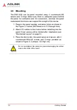
CAUTION:
Do not overtighten the screws to prevent damaging the rubber
seal on the back of the bezel.
Summary of Contents for DMI-1040
Page 8: ...viii Table of Contents This page intentionally left blank...
Page 10: ...x List of Figures This page intentionally left blank...
Page 12: ...xii List of Tables This page intentionally left blank...
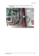
Page 27: ...Getting Started 15 DMI 1040 6 Disconnect the cable connecting the speakers to the main board...
Page 40: ...28 Getting Started This page intentionally left blank...
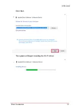
Page 45: ...Driver Installation 33 DMI 1040 Click Next The system will begin installing the Wi Fi driver...
Page 66: ...54 Driver Installation This page intentionally left blank...

