Connection Example
269
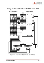
Figure 7-3: Connection of PCI-8164 with SANYO Driver
Wiring of PCI-8164 with SANYO AC Servo PY2
3
4
5
6
98
99
7
8
9
10
13
14
15
16
17
18
20
37
38
39
40
41
OUT1 +
OUT1 -
DIR +
DIR -
EX GND
EX +24V
SVON 1
ERC 1
ALM 1
INP 1
EA1 +
EA1 -
EB1 +
EB1 -
EZ1 +
EZ1 -
EX GND
PEL1
MEL1
PSD1
MSD1
ORG1
RDY 1
EX GND
11
12
EX +5V
19
PCI_8164 Axis 1
Servo Driver
SANYO
BL Super P
Series
Table
MEL
ORG
MSD
PSD
PEL
E
M
26
27
28
29
PPC
PPC
NPC
NPC
25
23
37
DC24V COM
DC24V
Servo ON
43
39
ALM1
General Out
32
PROT
3
Encoder A
4
Encoder A
5
6
Encoder B
Encoder B
7
Encoder C
8
Encoder C
33
NROT
CN1
EX +24V
100
49
DC24V
Summary of Contents for MPC-8164
Page 4: ......
Page 12: ......
Page 14: ...2 Introduction Figure 1 1 PCI 8164 block diagram ...
Page 50: ...38 Installation ...
Page 70: ...58 Signal Connections ...
Page 74: ...62 Signal Connections 3 17 1 Isolated input channels 3 17 2 Isolated output channels ...
Page 75: ...Signal Connections 63 3 17 3 Example of input connection ...
Page 76: ...64 Signal Connections 3 17 4 Example of output connections ...
Page 109: ...Operation Theory 97 ...
Page 110: ...98 Operation Theory ...
Page 111: ...Operation Theory 99 ...
Page 112: ...100 Operation Theory ...
Page 113: ...Operation Theory 101 ...
Page 148: ...136 Operation Theory Users can use this function to check if auto trigger is running Results ...
Page 280: ...268 Connection Example Figure 7 2 Connection of PCI 8164 with Panasonic Driver ...
Page 287: ...Connection Example 275 7 3 3 Mechanical Dimensions ...
Page 297: ...Connection Example 285 7 5 2 Mechanical Dimensions ...
Page 300: ...288 Connection Example 7 6 Wiring with DIN 814M J3A ...
Page 304: ...292 Connection Example 7 7 Wiring with DIN 814Y ...
Page 308: ...296 ...


