Signal Connections
47
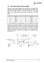
3.4 End-Limit Signals PEL and MEL
There are two end-limit signals PEL and MEL for each axis. PEL
indicates the end limit signal is in the plus direction and MEL indi-
cates the end limit signal is in the minus direction. The signal
names, pin numbers, and axis numbers are shown in the table
below.
A circuit diagram is provided below. The external limit switch
should have a contact capacity of +24V @ 6 mA minimum. Either
‘A-type’ (normal open) contact or ‘B-type’ (normal closed) contact
switches can be used. To set the type of switch, configure
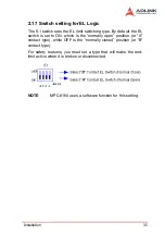
dipswitch S1/SW2. By default, all bits of S1 on the card are set to
ON (refer to section 2.10). For more details on EL operation, refer
to section 4.3.2.
CN2 Pin No Signal Name Axis # CN2 Pin No Signal Name Axis #
37
PEL1
1
87
PEL3
3
38
MEL1
1
88
MEL3
3
43
PEL2
2
93
PEL4
4
44
MEL2
2
94
MEL4
4
Summary of Contents for MPC-8164
Page 4: ......
Page 12: ......
Page 14: ...2 Introduction Figure 1 1 PCI 8164 block diagram ...
Page 50: ...38 Installation ...
Page 70: ...58 Signal Connections ...
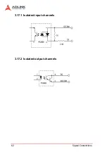
Page 74: ...62 Signal Connections 3 17 1 Isolated input channels 3 17 2 Isolated output channels ...
Page 75: ...Signal Connections 63 3 17 3 Example of input connection ...
Page 76: ...64 Signal Connections 3 17 4 Example of output connections ...
Page 109: ...Operation Theory 97 ...
Page 110: ...98 Operation Theory ...
Page 111: ...Operation Theory 99 ...
Page 112: ...100 Operation Theory ...
Page 113: ...Operation Theory 101 ...
Page 148: ...136 Operation Theory Users can use this function to check if auto trigger is running Results ...
Page 280: ...268 Connection Example Figure 7 2 Connection of PCI 8164 with Panasonic Driver ...
Page 287: ...Connection Example 275 7 3 3 Mechanical Dimensions ...
Page 297: ...Connection Example 285 7 5 2 Mechanical Dimensions ...
Page 300: ...288 Connection Example 7 6 Wiring with DIN 814M J3A ...
Page 304: ...292 Connection Example 7 7 Wiring with DIN 814Y ...
Page 308: ...296 ...

