Signal Connections
55
3.12 Position latch input pin: LTC
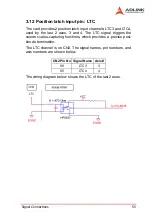
The card provides 2 position latch input channels: LTC3 and LTC4,
used by the last 2 axes, 3 and 4. The LTC signal triggers the
counter-value-capturing functions, which provides a precise posi-
tion determination.
The LTC channel is on CN2. The signal names, pin numbers, and
axis numbers are shown below.
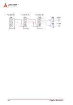
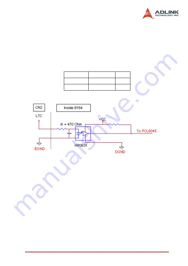
The wiring diagram below shows the LTC of the last 2 axes.
CN2 Pin No Signal Name Axis #
89
LTC3
3
95
LTC4
4
Summary of Contents for MPC-8164
Page 4: ......
Page 12: ......
Page 14: ...2 Introduction Figure 1 1 PCI 8164 block diagram ...
Page 50: ...38 Installation ...
Page 70: ...58 Signal Connections ...
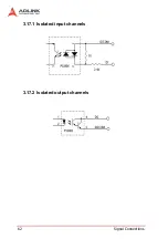
Page 74: ...62 Signal Connections 3 17 1 Isolated input channels 3 17 2 Isolated output channels ...
Page 75: ...Signal Connections 63 3 17 3 Example of input connection ...
Page 76: ...64 Signal Connections 3 17 4 Example of output connections ...
Page 109: ...Operation Theory 97 ...
Page 110: ...98 Operation Theory ...
Page 111: ...Operation Theory 99 ...
Page 112: ...100 Operation Theory ...
Page 113: ...Operation Theory 101 ...
Page 148: ...136 Operation Theory Users can use this function to check if auto trigger is running Results ...
Page 280: ...268 Connection Example Figure 7 2 Connection of PCI 8164 with Panasonic Driver ...
Page 287: ...Connection Example 275 7 3 3 Mechanical Dimensions ...
Page 297: ...Connection Example 285 7 5 2 Mechanical Dimensions ...
Page 300: ...288 Connection Example 7 6 Wiring with DIN 814M J3A ...
Page 304: ...292 Connection Example 7 7 Wiring with DIN 814Y ...
Page 308: ...296 ...

