Operation Theory
79
_8164_start_ta_move_xy(), _8164_start_ta_move_zu(),
_8164_start_sr_move_xy(), _8164_start_sr_move_zu(),
_8164_start_sa_move_xy(), _8164_start_sa_move_zu()
(Refer to section 6.7)
The second group allows you to freely assign the two target axes.
_8164_start_tr_line2(), _8164_start_sr_line2(),
_8164_start_ta_line2(), _8164_start_sa_line2()
(Refer to section 6.7)
The characters “t”, “s”, “r”, and “a” after _8164_start mean:
t – Trapezoidal profile
s – S-Curve profile
r – Relative motion
a – Absolute motion
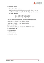
3-axis linear interpolation
Any three of the four axes of the card may perform 3-axis linear
interpolation. As shown the figure below, 3-axis linear interpola-
tion means to move the XYZ (if axes 0, 1, 2 are selected and
assigned to be X, Y, Z, respectively) position from P0 to P1,
starting and stopping simultaneously. The path is a straight line
in space.
Summary of Contents for MPC-8164
Page 4: ......
Page 12: ......
Page 14: ...2 Introduction Figure 1 1 PCI 8164 block diagram ...
Page 50: ...38 Installation ...
Page 70: ...58 Signal Connections ...
Page 74: ...62 Signal Connections 3 17 1 Isolated input channels 3 17 2 Isolated output channels ...
Page 75: ...Signal Connections 63 3 17 3 Example of input connection ...
Page 76: ...64 Signal Connections 3 17 4 Example of output connections ...
Page 109: ...Operation Theory 97 ...
Page 110: ...98 Operation Theory ...
Page 111: ...Operation Theory 99 ...
Page 112: ...100 Operation Theory ...
Page 113: ...Operation Theory 101 ...
Page 148: ...136 Operation Theory Users can use this function to check if auto trigger is running Results ...
Page 280: ...268 Connection Example Figure 7 2 Connection of PCI 8164 with Panasonic Driver ...
Page 287: ...Connection Example 275 7 3 3 Mechanical Dimensions ...
Page 297: ...Connection Example 285 7 5 2 Mechanical Dimensions ...
Page 300: ...288 Connection Example 7 6 Wiring with DIN 814M J3A ...
Page 304: ...292 Connection Example 7 7 Wiring with DIN 814Y ...
Page 308: ...296 ...


