12
•
Installation
u
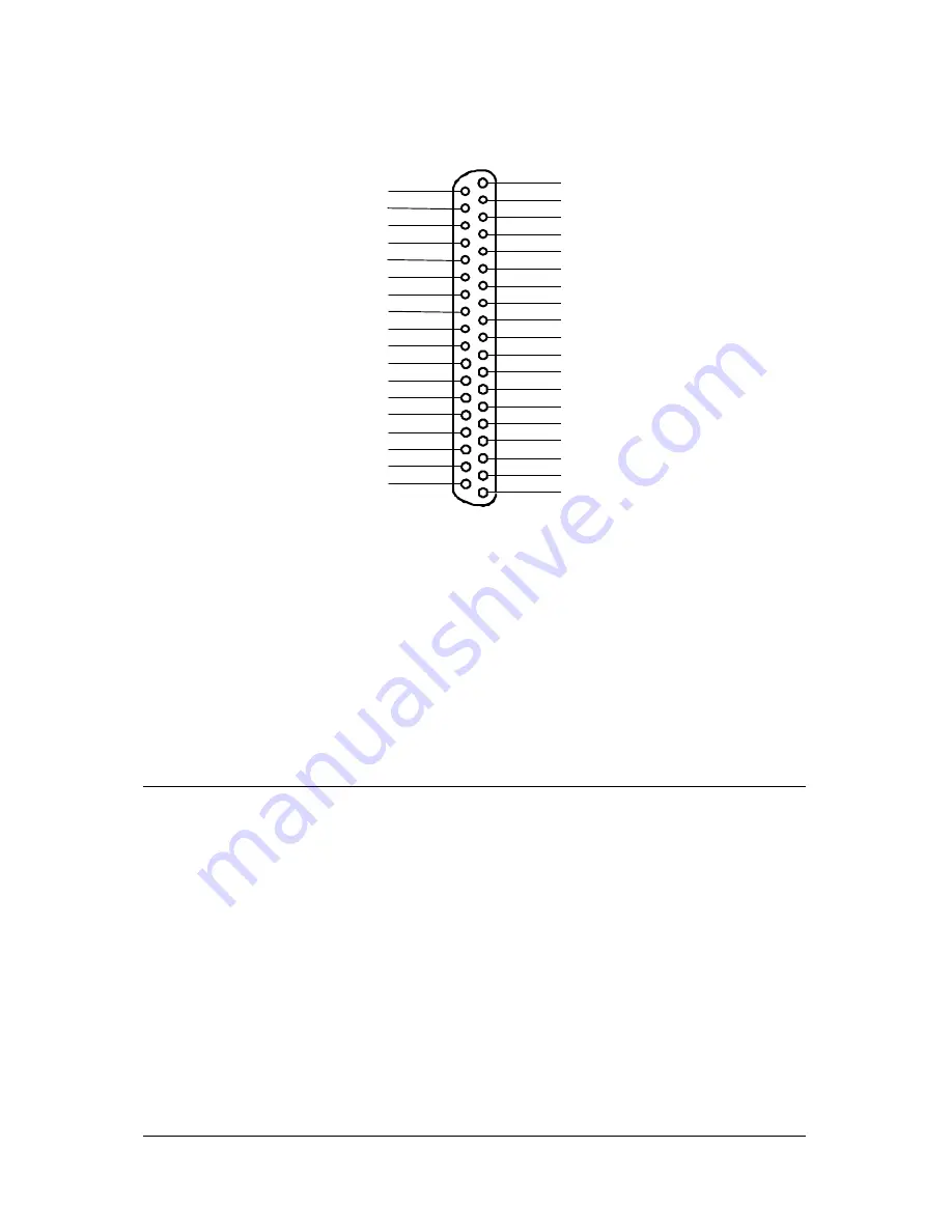
CN 3: Analog Input/Output, Extended I/O, Trigger Signals
AI2
1
2
3
4
5
6
7
8
9
10
11
12
13
14
15
16
17
18
19
21
22
23
24
25
26
27
28
29
30
20
31
32
33
34
35
36
37
AI3
AI10
AI9
AI8
AI1
AI0
AI6
AI7
AI5
AI4
AI13
AI14
AI12
AI11
DA Out
A.GND
AI15
A.GND
A.GND
A.GND
D.GND
+12V
D.GND
+5V
ExtTrg
CN3
N/C
PreTrg
N/C
EDO0
EDO1
EDO2
EDO3
EDI0
EDI1
EDI2
EDI3
Figure 2.5 Pin Assignment of CN3
Legend:
AI n
: Analog Input Channel
n
(single-ended)
DA Out
: Analog Output Channel
ExtTrg
: External A/D Trigger Signal
PreTrg
: Pre-Trigger Stop Signal
EDI n
: Extended Digital Input Channel n (0~3)
EDO n
: Extended Digital Output Channel n (0~3)
A.GND : Analog Signal Ground
D.GND : Digital Signal Ground
N.C
: No connection
2.8 Daughter Board Connection
The PCI-9111 can be connected with five different daughter boards,
ACLD-8125, ACLD-9137, 9138, 9182, 9185, and 9188. The functionality and
connections are specified as follows.
2.8.1 Connect with ACLD-8125
The ACLD-8125 has a 37-pin D-sub connector, which can connect with
PCI-9111 through 37-pin assemble cable. The most outstanding feature of this
daughter board is a CJC (cold junction compensation) circuit on board. You
can directly connect the thermocouple on the ACL-8125 board. The CJC only
suitable for High Gain version board.
Summary of Contents for NuDAQ PCI-9111DG
Page 1: ...NuDAQ PCI 9111DG HR Multi Functions Data Acquisition Card User s Guide ...
Page 4: ......
Page 10: ......

