34
•
Operation Theorem
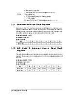
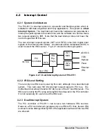
The application software can use the “_9111_Get_Irq_Status” function to
distinguish which interrupt is inserted. After servicing an IRQ signal, users
must check if another IRQ is also asserted, then clear current IRQ to allow the
next IRQ occurring.
The two IRQs are named as INT1 and INT2. INT1 comes from AD EOC or the
FIFO half-full flag. INT2 comes from timer‘s pacer output or the external
interrupt request. The sources of INT1 and INT2 are selective by the Interrupt
Control (ISC) Register.
Because of dual interrupt system, for example, you can use FIFO half-full and
external interrupt at the same time if your software ISR can distinguish these
two events.
4.2.4 Interrupt Source Control
There are two bits to control the IRQ sources of INT1 and INT2. Refer to
section 3.10 for the details of the bits. In addition, the PCI controller itself can
also control the using of the interrupt. For manipulating the interrupt system
more easily, ADLINK recommend you to use the function
_9111_INT_Source_Control to control the IRQ source so that you can disable
one or two of the IRQ sources.
Note that even you disable all the two IRQ sources without change the initial
condition of the PCI controller, the PCI BIOS still assigns an IRQ level to the
PCI card and it will occupy the PC resource. It is not suggested to re-design the
initial condition of the PCI card by users‘ own application software. If users
want to disable the IRQ level, please use the ADLINK’s software utility to
change the power on interrupt setting.
4.3 Extended Digital I/O Port
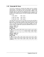
There are 4 extended digital input (EDI) signals and 4 extended digital output
(EDO) signals on CN3 connector. The 4 EDI signals are dedicated used as
input signal, however the 4 EDO signals can be used as digital input (Mode 1),
digital output (Mode 2) or channel number output (Mode 3).
For power on safety, the EDO channel is set to be input when power on initial.
To modify the configuration of the usage of the signals, please use the
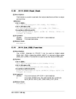
“_9111_Set_EDO_Function” in the library.
Note that when set the EDO function as channel number output (Mode 3), it
presents the high nibble (4 MSBs) of the channel number no matter manual
scan or auto scan mode.
Summary of Contents for NuDAQ PCI-9111DG
Page 1: ...NuDAQ PCI 9111DG HR Multi Functions Data Acquisition Card User s Guide ...
Page 4: ......
Page 10: ......

