Signal Connection
13
3
Signal Connection
This chapter describes the connector of PCI-9812/10, the signal
connection between PCI-9812/10 and external devices, and the
switch setting for different applications.
3.1 Connectors
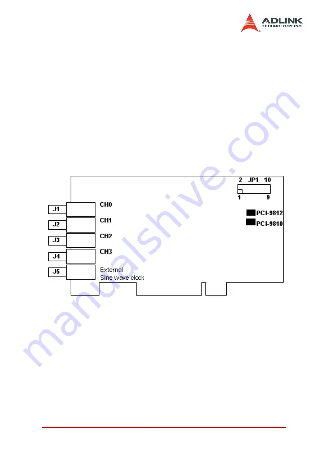
PCI-9812/10 connects to external devices through five BNC
connectors and one 10-pin dual-in-line header. Figure 3-1 shows
the location of these connectors.
Figure 3-1: Location of connectors
J1:
The J1 BNC connector is used for the input signal of channel 0
A/D converter.
J2:
The J2 BNC connector is used for the input signal of channel 1
A/D converter.
J3:
The J3 BNC connector is used for the input signal of channel 2
A/D converter.
Summary of Contents for NuDAQ PCI-9810
Page 4: ......
Page 10: ...vi ...
Page 19: ...Installation 9 2 3 PCI 9812 10 s Layout Figure 2 1 PCB Layout of the PCI 9812 10 ...
Page 22: ...12 ...
Page 40: ...30 ...
Page 78: ...68 Software Utility ...


