Connectors and Jumpers
13
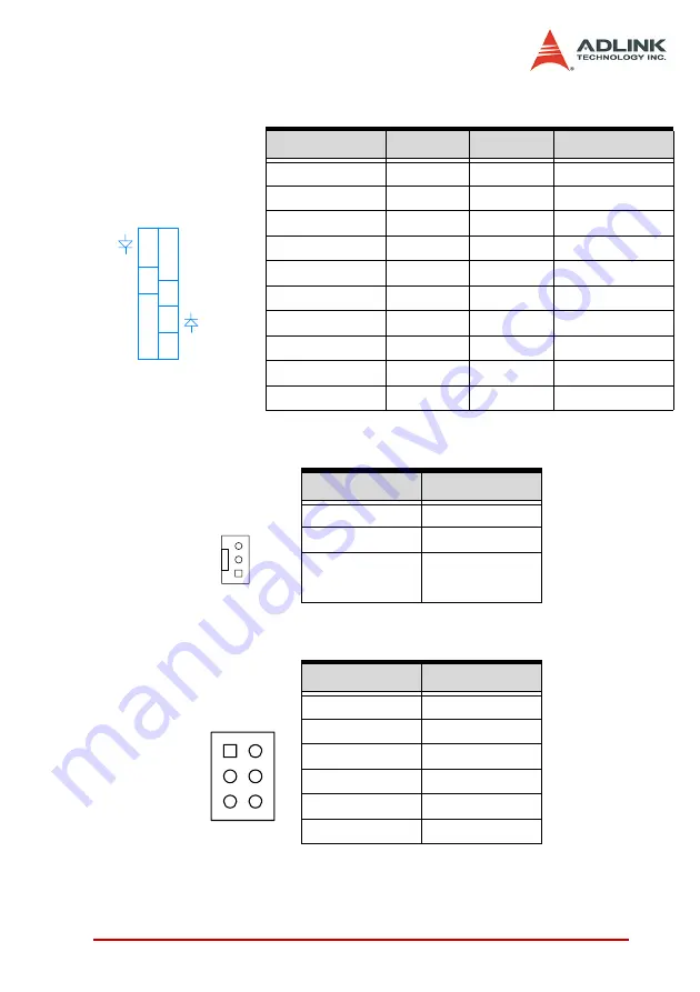
2.1.10 Miscellaneous Connector (CN18)
2.1.11 Fan Connector (CN20)
2.1.12 Audio-Out Pin Header (CN26)
Signal Name
Pin
Pin
Signal Name
1
11
BUZZER
NC
2
12
NC
PW_LED-
3
13
NC
KB_LOCK
4
14
+5V
GND
5
15
PW_GD
GND
6
16
GND
NC
7
17
HDD_LED-
PS_ON
8
18
5VSB
9
19
PW_BTN
PME#
10
20
GND
Pin
Signal Name
1
NC
2
+12V
3
GND
Pin
Signal Name
1
MIC In
2
ASGND
3
Line In Left
4
Line In Right
5
Line Out Left
6
Line Out Right
ATX POWER
CONN.
RESET BOTTON
16
12
KEYBOARD LOCK
19
2
14
8
11
7
POWER BOTTON
SPEAKER
(BUZZER)
6
4
18
HDD LED
3
x
20
9
13
17
1
5
15
POWER LED
1
3
2
6
2
1
5
Summary of Contents for NuPRO-796 Series
Page 4: ......
Page 13: ...Introduction 5 1 4 NuPRO 796 Functional Diagram Figure 1 1 NuPRO 796 Block Diagram ...
Page 14: ...6 Introduction 1 5 NuPRO 796 Mechanical Diagram Figure 1 2 NuPRO 796 Carrier Board Layout ...
Page 28: ...20 Connectors and Jumpers ...
Page 45: ...Phoenix Award BIOS 37 4 5 3 Onboard Audio Enable or Disable ...
Page 68: ...60 Watchdog Timer ...


