Hardware Information
17
NuPRO-A40H
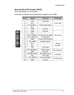
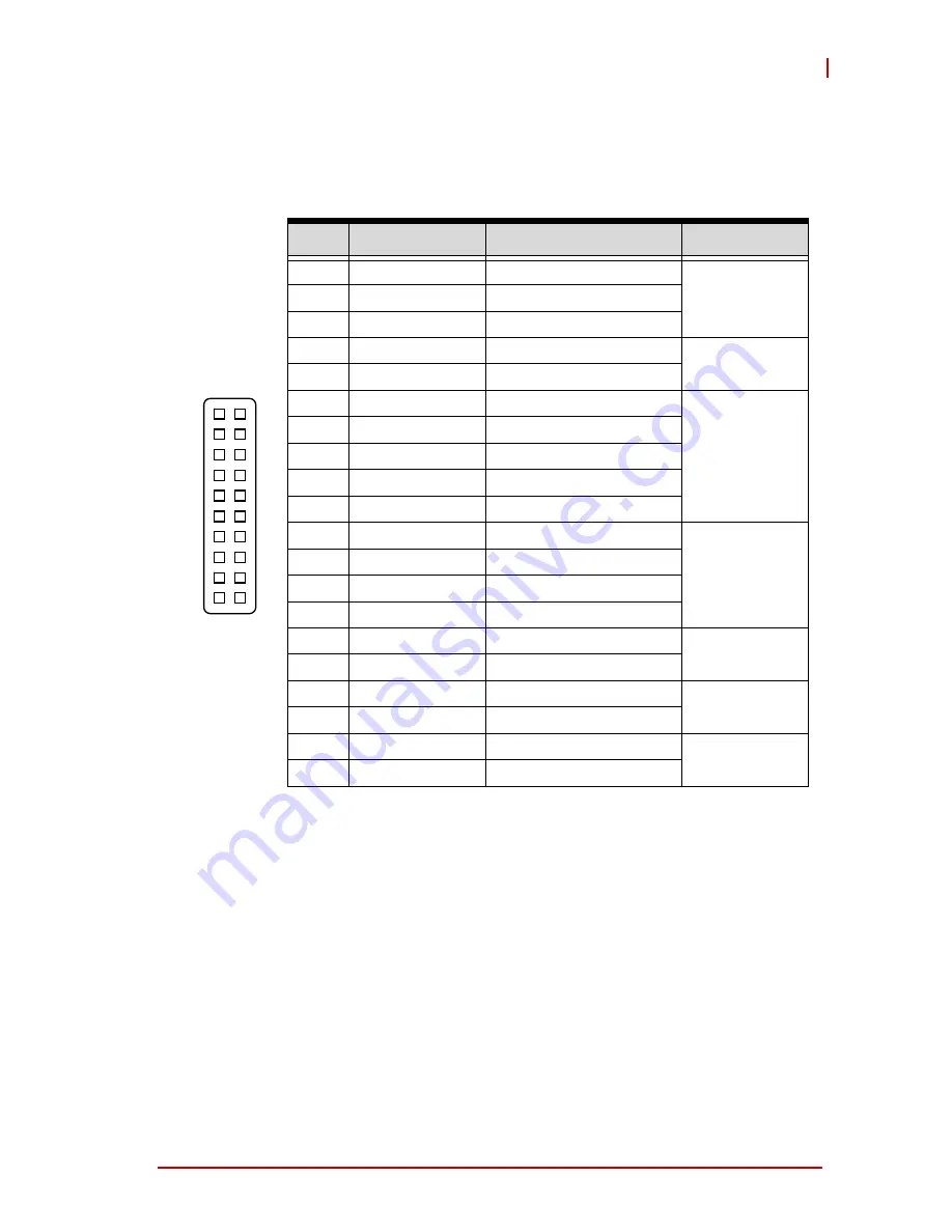
System Panel Pin Header (CN23)
(2x10 pin header, 2.54mm pitch)
Connects to chassis-mounted buttons, speakers, and LEDs.
Pin #
Signal
Function
Pin Group
1
P5V
+5V Power
Power LED
2
NC
3
HC_PLED-L
Power LED signal
4
NC
5
GND
Ground
6
GND
Ground
ATX Power
7
NC
8
ATX_PSON-L ATX Power-On signal
9
P5V_SB_ATX
+5V Standby
10
PMEJ
Power Control signal
11
HC_SPKR
Speaker signal
Chassis
Speaker
12
NC
13
NC
14
P5V
+5V Power
15
HC_RSTBN-L
Reset signal
Reset Button
16
GND
Ground
17
HDLED_PWR
HDD LED signal
HDD LED
18
P5V
+5V Power
19
HC_PBTNJ
Power-On signal
Power Button
20
GND
Ground
1
10
20
11
Summary of Contents for NuPRO-A40H
Page 6: ...vi Preface This page intentionally left blank ...
Page 9: ...Table of Contents ix NuPRO A40H Important Safety Instructions 83 Getting Service 85 ...
Page 10: ...x Table of Contents This page intentionally left blank ...
Page 12: ...xii List of Figures This page intentionally left blank ...
Page 14: ...xiv List of Tables This page intentionally left blank ...
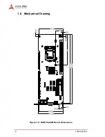
Page 22: ...8 Introduction 1 6 Mechanical Drawing Figure 1 2 NuPRO A40H Board Dimensions ...
Page 26: ...12 Introduction This page intentionally left blank ...
Page 40: ...26 Hardware Information This page intentionally left blank ...
Page 76: ...62 BIOS Setup Memory Configuration Memory Remap Enabled or Disable Memory remap above 4G ...
Page 88: ...74 Watchdog Timer This page intentionally left blank ...
Page 96: ...82 System Resources This page intentionally left blank ...

