Signal Connections
27
3.4
End-Limit Signals PEL and MEL
There are two end-limit signals PEL and MEL for each axis. PEL
indicates the end limit signal is in the plus direction and MEL indi-
cates the end limit signal is in the minus direction. The signal
names, pin numbers, and axis numbers are shown in the table
below:
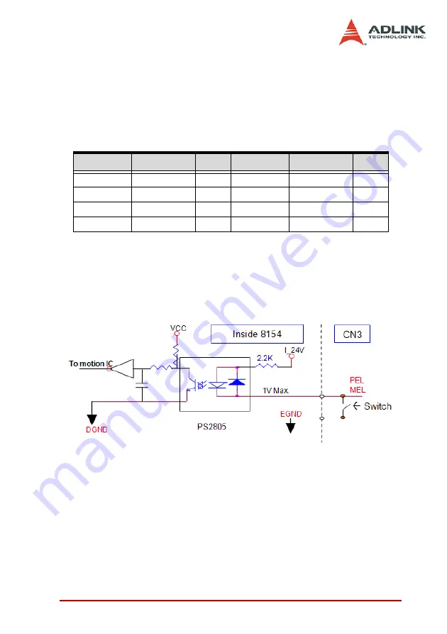
A circuit diagram is shown in the diagram below. The external limit
switch should have a contact capacity of +24V @ 8mA minimum.
Either ‘A-type’ (normal open) contact or ‘B-type’ (normal closed)
contact switches can be used. To set the active logic of the exter-
nal limit signal, please refer to the explanation of
_8154_set_limit_logic function.
CN3 Pin No Signal Name Axis # CN3 Pin No Signal Name Axis #
37
PEL0
0
38
MEL0
0
43
PEL1
1
44
MEL1
1
87
PEL2
2
88
MEL2
2
93
PEL3
3
94
MEL3
3
Summary of Contents for PCI-8154
Page 4: ......
Page 28: ...18 Installation ...
Page 48: ...38 Signal Connections ...
Page 98: ...88 Operation Theory ...
Page 106: ...96 MotionCreatorPro In the IO_Config_2 menu users can configure LTC SD PCS and Select_Input ...
Page 130: ...120 MotionCreatorPro ...
Page 206: ...196 Function Library Pos Latch data Position ...
Page 224: ...214 Function Library ...
Page 226: ...214 Connection Example ...

