Motion Creator
145
This frame provides a flexible choice to configure the trigger. Once
the signal is triggered, the data from the four channels will be plot-
ted on the response diagram.
X
Source: select one of the channel signal to be the trigger
source
X
Value: trigger value
X
Slope: specify the rising edge or falling edge trigger
X
Sample Number: total amount of the gathering data
X
Pretrigger sample No.: amount of the pretrigger data
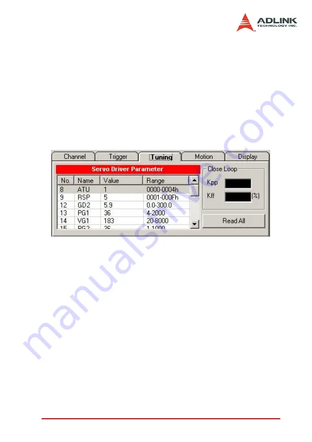
Figure 5-12: Parameter Tuning Frame
This frame affords an easy way to access a set of fundamental
servo parameter.
Read All: read the current servo parameter
Channel Selection Frame
This frame is used to set the signal of each channel.
Sample interval: the sample interval between signals. The units of
the X-Axis is sample interval.
Summary of Contents for PCI-8366+
Page 4: ......
Page 14: ...x List of Figures ...
Page 17: ...Introduction 3 Figure 1 3 Flowchart for Building an Application ...
Page 26: ...12 Installation 2 2 PCI 8372 8366 Outline Drawing Figure 2 1 PCI 8372 8366 Mechanical Drawing ...
Page 31: ...Installation 17 2 Press HPI boot ...
Page 32: ...18 Installation 3 Press Flash DL button and select a kernel4 hex ...
Page 34: ...20 Installation Figure 2 3 SSCNET Communication Test Utility ...
Page 49: ...Signal Connections 35 Figure 3 9 Skin Type ...
Page 144: ...130 Operation Theory ...
Page 149: ...Motion Creator 135 Figure 5 6 Software Version Information ...
Page 160: ...146 Motion Creator Figure 5 13 Channel Selection Frame Figure 5 14 Motion Frame ...


