List of Tables
v
List of Tables
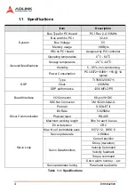
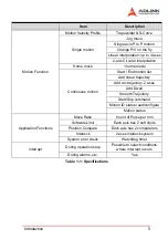
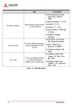
Table 1-1: Specifications ........................................................... 4
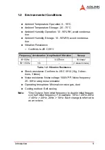
Table 1-2: Vibration Resistance ................................................. 9
Table 2-1: CN1 Pin Assignment .............................................. 22
Table 2-2: CN5 Pin Assignment .............................................. 23
Table 2-3: SP1 Pin Assignment ............................................... 24
Table 2-4: CN3 Pin Assignment .............................................. 25
Table 2-5: HS1A - HS2B Pin Assignment ................................ 26
Table 3-1: Encoder Feedback Signals: EA, EB and EZ .......... 29
Table 3-2: Encoder Power ....................................................... 31
Table 3-3: PEL, MEL, ORG, EMG and General Purpose DI ... 32
Table 3-4: General Purpose DO Pinout ................................... 36
Table 3-5: TTL Output Pinout .................................................. 37
Table 3-6: Analog Output Pinout ............................................. 38
Table 3-7: Analog Input Pinout ................................................ 38
Table 3-8: Pulse Output Pinout ................................................ 39
Table 4-1: start_tr_move Data Table ....................................... 44
Table 4-2: set_position_compensate Values ........................... 58
Table 4-3: Axis Status .............................................................. 74
Table 4-4: Motion Status .......................................................... 75
Table 4-5: Encoder Resistor .................................................... 78
Table 4-6: MR-J2SB Parameters ............................................. 84
Table 4-7: Monitoring Targets .................................................. 88
Table 4-8: Axis Parameters ..................................................... 91
Table 4-9: Data Array Offset .................................................... 93
Table 4-10: Servo Bit Information .............................................. 93
Table 4-11: Selectable Gains .................................................... 98
Table 4-12: Notch Frequency Settings ...................................... 99
Table 4-13: Notch Gain Settings .............................................. 100
Table 4-14: Suppression Control Settings ............................... 100
Table 4-15: Axis Interrupts ....................................................... 104
Table 4-16: System Interrupts ................................................. 104
Table 4-17: GPIO Interrupts .................................................... 104
Table 4-18: Pattern Index ........................................................ 118
Table 4-19: Sequences ............................................................ 120
Table 6-1: MR-J2S-B Alarm List ............................................ 163
Table 6-2: MR-J2S-B Warning List ........................................ 165
Table 6-3: Driver Parameter List ............................................ 166
Table 6-4: Card Initial Procedure ........................................... 168
Summary of Contents for PCI-8366+
Page 4: ......
Page 14: ...x List of Figures ...
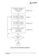
Page 17: ...Introduction 3 Figure 1 3 Flowchart for Building an Application ...
Page 26: ...12 Installation 2 2 PCI 8372 8366 Outline Drawing Figure 2 1 PCI 8372 8366 Mechanical Drawing ...
Page 31: ...Installation 17 2 Press HPI boot ...
Page 32: ...18 Installation 3 Press Flash DL button and select a kernel4 hex ...
Page 34: ...20 Installation Figure 2 3 SSCNET Communication Test Utility ...
Page 49: ...Signal Connections 35 Figure 3 9 Skin Type ...
Page 144: ...130 Operation Theory ...
Page 149: ...Motion Creator 135 Figure 5 6 Software Version Information ...
Page 160: ...146 Motion Creator Figure 5 13 Channel Selection Frame Figure 5 14 Motion Frame ...


