78
Operation
Theory
Below are examples of connecting the input signals with an
external circuit. The input circuit can be connected to an
encoder or motor driver, if it is equipped with: (1) a differential
line driver or (2) an open collector output.
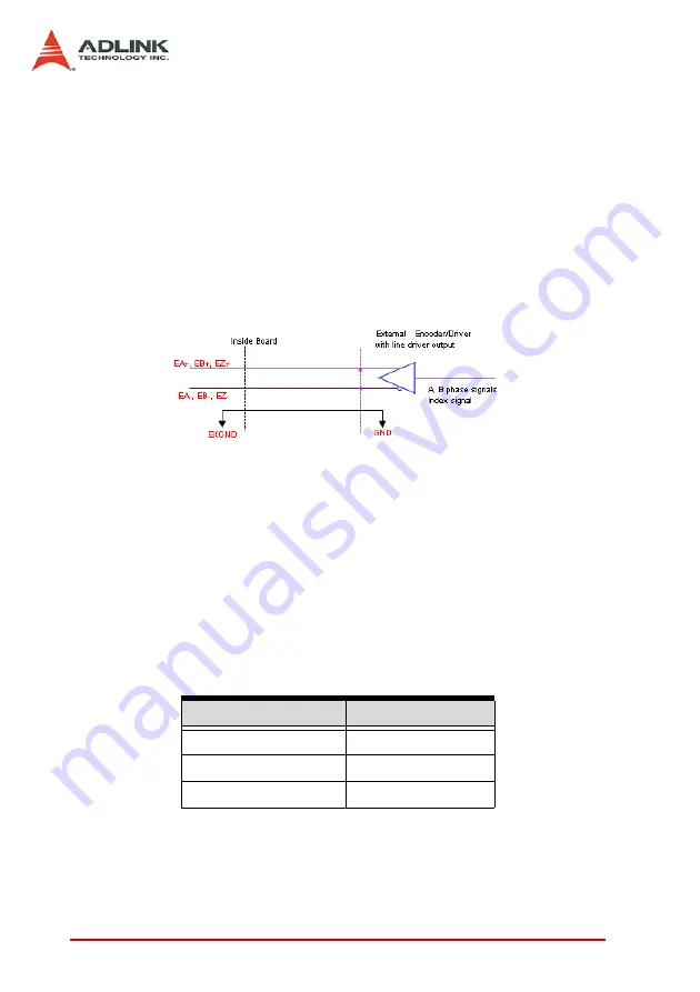
Connection to Line Driver Output
To drive the SSCNET board encoder input, the driver output
must provide at least 3.5V across the differential pairs with at
least 6 mA driving capacity. The ground level of the two sides
must also be tied together.
Figure 4-31: Line Driver Circuit
Connection to Open Collector Output
To connect with an open collector output, an external power
supply is necessary. Some motor drivers can provide the
power source. The connection between the SSCNET board,
encoder, and the power supply is shown in the diagram below.
Note that an external current limiting resistor R is necessary to
protect the SSCNET board input circuit. The following table
lists the suggested resistor values according to the encoder
power supply.
X
+If=6mA max.
Encoder Power (VDD) External Resistor R
+5V
0
Ω
(None)
+12V
1.8k
Ω
+24V
4.3k
Ω
Table 4-5: Encoder Resistor
Summary of Contents for PCI-8366+
Page 4: ......
Page 14: ...x List of Figures ...
Page 17: ...Introduction 3 Figure 1 3 Flowchart for Building an Application ...
Page 26: ...12 Installation 2 2 PCI 8372 8366 Outline Drawing Figure 2 1 PCI 8372 8366 Mechanical Drawing ...
Page 31: ...Installation 17 2 Press HPI boot ...
Page 32: ...18 Installation 3 Press Flash DL button and select a kernel4 hex ...
Page 34: ...20 Installation Figure 2 3 SSCNET Communication Test Utility ...
Page 49: ...Signal Connections 35 Figure 3 9 Skin Type ...
Page 144: ...130 Operation Theory ...
Page 149: ...Motion Creator 135 Figure 5 6 Software Version Information ...
Page 160: ...146 Motion Creator Figure 5 13 Channel Selection Frame Figure 5 14 Motion Frame ...


