Installation
25
Note
:
*MDI# is for general purpose input if it is not used for motion
2.9
CN3 Pin Assignment: TTL output Connector on
bracket
31
OUT2+
O
Pulse signal (+)
65
DIR1-
O
Dir. signal (-)
32
OUT2-
O
Pulse signal (-)
66
DA1
O
Analog Output
33
DIR2+
O
Dir. signal (+)
67
DA2
O
Analog Output
34
DIR2-
O
Dir. signal (-)
68
A_COM
-
Analog Ground
No Name I/O Function Axis No Name I/O
Function Axis
1
GND
-
Signal Ground
2
GND
-
Signal Ground
3
TDO1
O
TTL Output 1
4
TDO2
O
TTL Output 2
5
TDO3
O
TTL Output 3
6
TDO4
O
TTL Output 4
7
TDO5
O
TTL Output 5
8
TDO6
O
TTL Output 6
9
+5V
-
+5V Supply
10
NC
-
Not connected pin
Table 2-4: CN3 Pin Assignment
No
Name
I/O
Function Axis
No
Name
I/O
Function Axis
Table 2-3: SP1 Pin Assignment
Summary of Contents for PCI-8366+
Page 4: ......
Page 14: ...x List of Figures ...
Page 17: ...Introduction 3 Figure 1 3 Flowchart for Building an Application ...
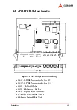
Page 26: ...12 Installation 2 2 PCI 8372 8366 Outline Drawing Figure 2 1 PCI 8372 8366 Mechanical Drawing ...
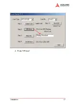
Page 31: ...Installation 17 2 Press HPI boot ...
Page 32: ...18 Installation 3 Press Flash DL button and select a kernel4 hex ...
Page 34: ...20 Installation Figure 2 3 SSCNET Communication Test Utility ...
Page 49: ...Signal Connections 35 Figure 3 9 Skin Type ...
Page 144: ...130 Operation Theory ...
Page 149: ...Motion Creator 135 Figure 5 6 Software Version Information ...
Page 160: ...146 Motion Creator Figure 5 13 Channel Selection Frame Figure 5 14 Motion Frame ...


