
Interfaces
39
Q7-BASE
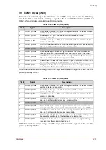
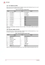
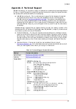
3.42 EN_V3P3S Select (CN92)
Table 3-43 lists the pin signals of the EN_V3P3S Select jumper header, which provides 3 pins in
a single row with 2.00mm pitch.
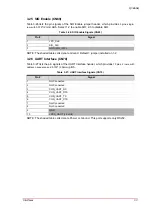
3.43 USB3_CN_p / USB3_mPCIe_p Select (CN93)
Table 3-44 lists the pin signals of the USB3_CN_p / USB3_mPCIe_p Select jumper header,
which provides 3 pins in a single row with 2.00mm pitch.
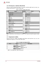
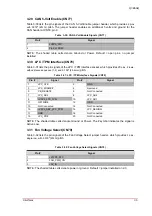
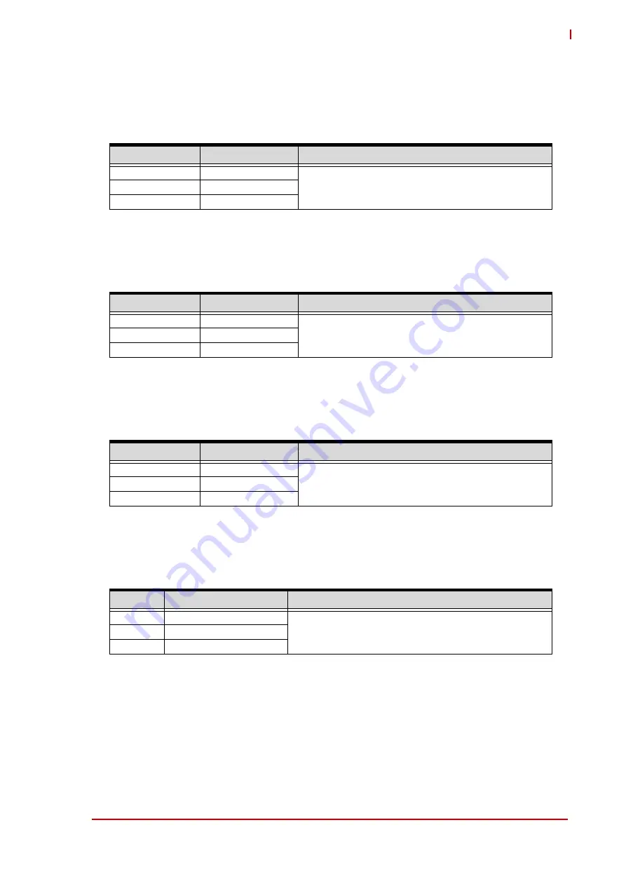
3.44 USB3_CN_n / USB3_mPCIe_n Select (CN94)
Table 3-45 lists the pin signals of the USB3_CN_n / USB3_mPCIe_n Select jumper header,
which provides 3 pins in a single row with 2.00mm pitch.
3.45 USB OTG Power Control (CN95)
Table 3-46 lists the pin signals of the USB OTG Power Control jumper header, which provides 3
pins in a single row with 2.00mm pitch.
Table 3-43: EN_V3P3S Select (CN92)
Pin #
Signal
Jumper Position
1
+V5_IN
• Jumper Installed 1-2 - ATX mode
• Jumper Installed 2-3 - SUS_S3# (
Default
)
2
EN_V3P3S
3
SUS_S3#
Table 3-44: USB3_CN_p / USB3_mPCIe_p Select (CN93)
Pin #
Signal
Jumper Position
1
USB3_CN_p
• Jumper Installed 1-2 - USB connector (
Default
)
• Jumper Installed 2-3 - MiniPCIe
2
USB3_L_p
3
USB3_mPCIe_p
Table 3-45: USB3_CN_n / USB3_mPCIe_p Select (CN94)
Pin #
Signal
Jumper Position
1
USB3_CN_n
• Jumper Installed 1-2 - USB connector (
Default
)
• Jumper Installed 2-3 - MiniPCIe
2
USB3_L_n
3
USB3_mPCIe_n
Table 3-46: USB OTG Power Control (CN95)
Pin #
Signal
Jumper Position
1
USB_DRIVE_VBUS
• Jumper Installed 1-2 - USB_DRIVE_VBUS (
Default
)
• Jumper Installed 2-3 - USB_OTG_ID
2
USB02_PWREN
3
USB1_OTG_ID_INV


