18
System Layout
Leading
EDGE COMPUTING
adapter cable, DisplayPort to DVI adapter cable, or DisplayPort to
HDMI adapter cable and DisplayPort cable.
Table 3-3: DisplayPort Pin Definition
Table 3-4: Applicable Cable Types
3.1.5
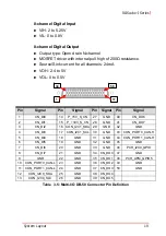
Multi-I/O DB-50 Connector
The ROScube-I provides comprehensive I/O for autonomous
robotics including two channels CANbus, two channels I2C and
eight channels DI/DO.
Pin
Signal
Pin
Signal
1
C 11
GND
2
GND
12
CN_DDPx3-
3
CN_DDPx0-
13
CN_DDPx_AUX_SEL
4
C 14
CN_DDPx_CONFIG2
5
GND
15
CN_D
6
CN_DDPx1-
16
GND
7
C 17
CN_DDPx_AUX-
8
GND
18
CN_DDPx_HPD
9
CN_DDPx2-
19
GND
10
C 20
+V3.3_DDPx_PWR_CN
P/N
Description
30-01119-0010 Active DisplayPort to HDMI adapter cable
30-01120-0010 Active DisplayPort to DVI adapter cable
30-01121-0010 Active DisplayPort to VGA adapter cable
1
2
19
20
Summary of Contents for ROScube-I Series
Page 8: ...viii List of Tables Leading EDGE COMPUTING This page intentionally left blank ...
Page 10: ...x List of Figures Leading EDGE COMPUTING This page intentionally left blank ...
Page 24: ...14 Specifications Leading EDGE COMPUTING This page intentionally left blank ...
Page 42: ...32 System Layout Leading EDGE COMPUTING This page intentionally left blank ...
Page 46: ...36 Getting Started Leading EDGE COMPUTING This page intentionally left blank ...
Page 52: ...42 BIOS Setup Leading EDGE COMPUTING B 2 1 CPU Configuration ...
Page 94: ...84 Consignes de Sécurité Importante Leading EDGE COMPUTING This page intentionally left blank ...


