Getting Started
19
4. Getting
Started
The chapter describes the steps needed to install optional expansion modules onto ROScube Pico series and
begin using it in your application.
4.1. Connect the DC plug adapter cable
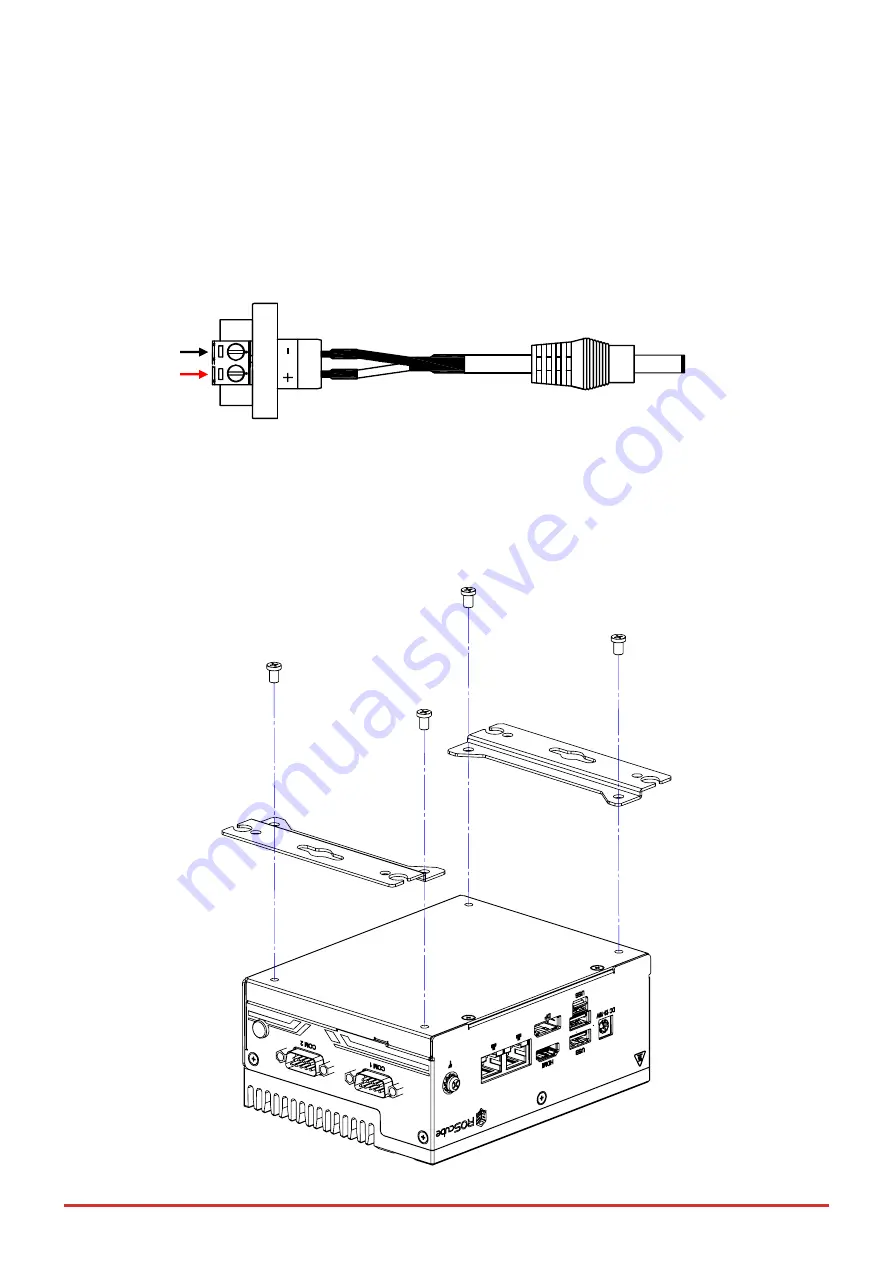
Locate the DC plug adapter cable, included in the accessory box (shown below). Insert to the DC output wires of
the AC adapter into the terminal block P1 as indicated: negative (black) to “-“ and positive (red) to “+”.
Insert the DC plug P2 into the DC power input jack on the front panel (see Figure 3: Front Panel I/O on page 7)
4.2. Mounting the ROSCube Pico TGL
Attach the 2 included wall-mount brackets to the chassis as shown below.
P1
P2


