background image

14.4Kbps Modem Option Installation

8

ADP Incorporated


 Note

Be aware that each RS-485 device located at the ends of the RS-485 network 
must be set for termination and biasing.

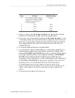
5. Install plastic standoffs on the timeclock’s main board to secure the modem 

option. (Refer to the earlier 14.4Kbps Modem option figure for reference).

6. Plug the modem option  into connector J2 on the main board, and seat it on the 

standoffs.

7. Plug one end of the supplied 7-foot telco cable into the modem option’s RJ-11 

connector (J1).

8. Feed the telco cable through one of the available openings in the base of the unit.

9. Reconnect power to the timeclock.

a. If the timeclock is equipped with a 12 VDC lead-acid backup

battery, reconnect the backup battery board's cable to connector TB3
on the main board.

b. Reconnect the timeclock to its external power source:

If the timeclock is powered using a DC wall supply, plug the wall supply’s 
cable into connector J1 on the #6600177 board, or J3 on the #6600186 
board.

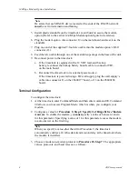
Terminal Configuration

To configure the timeclock:

1. At the timeclock, enter Command Mode and then enter command 90. Command 

90 allows you to access Program Mode, which is where you configure your 
modem. 

2. Configure a value for Procedure 9, Step 1: Specify # of Rings Before Modem 

Answers. To enable the modem, you must specify a value of between 1 and 4 
for this parameter. Specifying a value of 1 for this parameter causes the modem 
to auto-answer on the first ring.


 Note

When you specify a value other than 0 for Procedure 9, the timeclock 
automatically enables a 10 mSec data transmission delay at the timeclock where 
the modem is installed.

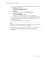
3. Choose a modem-to-modem protocol in Procedure 10, Step 7. The appropriate 

values, protocols, and baud rates are as follows:

Summary of Contents for 14.4Kbps

Page 1: ...Document Part Number 4701357 002 Document Revision B This manual provides installation and troubleshooting instructions for the 14 4Kbps Modem option 14 4Kbps Modem Option Installation Guide ...

Page 2: ...quipment complies with the limits for a Class A digital device pursuant to Part 15 of FCC Rules These limits provide reasonable protection against harmful interference when this equipment is operated in a commercial environment This equipment generates uses and can radiate radio frequency energy If it is not installed and used in accordance with the instruction manual it can cause harmful interfer...

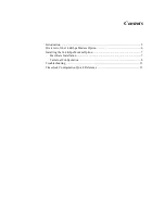
Page 3: ...ts Introduction 5 Overview of the 14 4Kbps Modem Option 6 Installing the 14 4Kbps Modem Option 7 Hardware Installation 7 Terminal Configuration 8 Troubleshooting 11 Timeclock Configuration Quick Reference 13 ...

Page 4: ...iv ADP Incorporated ...

Page 5: ...ndustry standard modem protocols with speeds other than 14 4Kbps The 14 4Kbps Modem option is compatible with timeclocks equipped with the following Main boards with a part number of 6600177 00X or 6600186 00X Rev A or later Boot PROM software version 2B00 or later for the 6600177 00X board or 3B00 or later for the 6600186 00X board FLASH EEPROM time and attendance application version 400 5C or la...

Page 6: ...tion about the modem option The LEDs are described as follows Ring Indicator RI The RI LED lights when the RS 485 modem option is being called from eTIME Carrier Detect CD The CD LED lights when the RS 485 modem option has detected a carrier signal thus signifying a connection between modems Receive Data RD The RD LED lights when the timeclock is receiving data from eTIME Send Data SD The SD LED l...

Page 7: ...timeclock configuration Follow the steps in the two sections that follow to install the 14 4Kbps Modem option Hardware Installation To install the 14 4Kbps Modem option 1 Collect the timeclock data using the eTIME software 2 Using an 8 32 security head wrench unlock and open the timeclock s front cover a If the timeclock is equipped with a 12 VDC lead acid backup battery disconnect the backup batt...

Page 8: ...main board b Reconnect the timeclock to its external power source If the timeclock is powered using a DC wall supply plug the wall supply s cable into connector J1 on the 6600177 board or J3 on the 6600186 board Terminal Configuration To configure the timeclock 1 At the timeclock enter Command Mode and then enter command 90 Command 90 allows you to access Program Mode which is where you configure ...

Page 9: ... if the message NO MODEM ALLOCATED appears here it indicates that the modem has not been enabled and thus is not recognized Similarly a NO MODEM ACTIVE message indicates that the modem has been enabled but is not responding For more information see the Troubleshooting section that follows An INTERNAL 2400b MODEM message indicates a modem has been found and is responding However the responding mode...

Page 10: ...e plus 4 for the end of text indicator 10 At the eTIME site be sure that the modem is connected to the PC and working properly Follow the instructions supplied by the modem manufacturer when making this connection 11 Connect the eTIME modem to a live phone line Note Between the eTIME PC and eTIME modem it is recommended that you turn off hardware RTS CTS flow control for DOS and turn it on for Win...

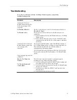
Page 11: ...odule produces an error message at the timeclock The currently installed modem either the 2400 baud modem or the 14 4Kbps Modem option is failing its internal loopback test This command should not be run while the modem is communicating with another modem Verify the modem board installation and the timeclock setup for the respective modem 2400 baud modem or 14 4Kbps Modem option These messages app...

Page 12: ... for a lower rate modem such as V 22bis If the modem negotiation is timing out configure your eTIME PC modem and 14 4Kbps Modem option for the same telephone line rate that is 1200 2400 9600 or 14 4 Communication is initially established but the modems hang up immediately Verify that the error correction and data compression settings on off are the same for the eTIME PC modem and the 14 4Kbps Mode...

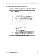
Page 13: ...or correction data compression Procedure 10 Step 9 6 Exit Program Mode and return to Command Mode 7 Use command 118 to verify that the timeclock recognizes a modem and then confirm all of your modem selections 8 Close and secure the timeclock s front cover 9 Configure all other timeclocks which are connected at the remote site by way of RS 485 with these values Modem Option Modem not installed Con...

Page 14: ...14 4Kbps Modem Option Installation 14 ADP Incorporated ...

Reviews: