background image


IM-MAH-0662403-07 

April 2012 


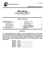
Installation Instructions


MX Series  

Indoor Modular Blowers 

Electric or Hot Water Heat 


Table of Contents


AIR HANDLER SAFETY


INSTALLATION REQUIREMENTS


Tools and Parts  


Location Requirements   


Installation Configurations 


Electrical Requirements  


5


Ductwork Requirements 


5


INSTALLATION INSTRUCTIONS


5


Inspect Shipment


5


     Blower and Coil Assembly 


5


     Install Ductwork 


     Make Electrical Connections


      Hydronic Coil Installation 


Complete Installation  


                        14 

SEQUENCE OF OPERATION   


17


AIR HANDLER MAINTENANCE

                                   18        

ASSISTANCE OR SERVICE


           18 

WARRANTY 


19 


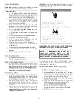
! WARNING ! 


To install the MX Series Air Handler in the horizontal position a (2”) clearance 
must be maintained between the apex of the evaporator coil and the top of the 
Coil’s Cabinet.  Therefore, the ADP Multi-position Evaporator Coils listed below 
cannot  be used in the horizontal position with the MX Series Air Handler.  The 
HD Series and V Series dedicated  horizontal  coils  are recommended for these 
applications.    

Model #    _ A 0 7 _ _ _ _ _ _ _ _ _ _ _ _ _ _  
Model #    _ A 1 5 _ _ _ _ _ _ _ _ _ _ _ _ _ _  

Model #    _ E 2 7 _ _ _ _ _ _ _ _ _ _ _ _ _ _  
Model #    _ E 3 7 _ _ _ _ _ _ _ _ _ _ _ _ _ _  
Model #    _ E 4 8 _ _ _ _ _ _ _ _ _ _ _ _ _ _  
Model #    _ E 5 0 _ _ _ _ _ _ _ _ _ _ _ _ _ _  


Summary of Contents for MX Series

Page 1: ...LER MAINTENANCE 18 ASSISTANCE OR SERVICE 18 WARRANTY 19 WARNING To install the MX Series Air Handler in the horizontal position a 2 clearance must be maintained between the apex of the evaporator coil and the top of the Coil s Cabinet Therefore the ADP Multi position Evaporator Coils listed below cannot be used in the horizontal position with the MX Series Air Handler The HD Series and V Series de...

Page 2: ...emove the cabinet knockouts until it has been determined which knockouts will need to be removed for the installation Select the final installation position that best suits the site conditions Consider required clearances space and routing requirements for refrigerant line condensate disposal filters ductwork wiring and accessibility for service Refer to the rating plate on the blower section for ...

Page 3: ... models 360 square inches for 12 models 450 square inches for 16 and 20 models If the free area is not known assume a 25 free area for wood or a 75 free area for metal louvers or grilles Using the louver dimensions and the 25 or 75 assumption determine if the louver open area meets the minimum open area listed above If the return air plenum is used the return air grille should be immediately in fr...

Page 4: ...ondary drain should be trapped and piped When an evaporator coil is installed in an attic or above a finished ceiling an auxiliary drain pan should be provided under the MX Series Air Handler and coil as specified by most local building codes Conversion from Vertical to Horizontal The MX Series Air Handler can be converted from operating in a vertical to a horizontal position by installing support...

Page 5: ...r before turning or branching off plenum into duct runs The plenum forms an extension of the blower housing and minimizes air expansion losses from the blower Installation Instructions Inspect Shipment The blower section is completely factory assembled and all components are performance tested Each unit consists of a blower assembly and controls in an insulated galvanized steel factory finished en...

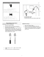
Page 6: ...lot 4 Position the blower section up against the coil opening Front of blower left connected to a HD coil right Back of HD coil left connected to a blower right 5 Fasten duct flanges of coil to duct flanges of blower section with screws to secure MX Series Air Handler Install Ductwork IMPORTANT Install ductwork in accordance with NFPA 90B and any local codes Connect supply air duct to the flange o...

Page 7: ...Handler black to black and yellow to yellow For 120 Volts connect the field supply wires to the MX Series Air Handler black to black and white to white 5 Connect ground wire to ground terminal marked GND 6 Replace the MX Series Air Handler access panel 208 Volt Conversion 1 Disconnect all power supplies 2 Remove the MX Series Air Handler access panel 3 Move the 2 connected black transformer leads ...

Page 8: ...eaker orientation change is required by UL 1995 Article 26 18 25 Sep 2005 NOTICE Copper tubing is recommended but other approved materials are acceptable WARNING Solder joints on domestic water lines are to be made with NO LEAD SOLDER NOTICE The State of MA requires the use of a pump timer on domestic water applications to periodically circulate water during the off cycle This pump timer requireme...

Page 9: ...r heater recovery efficiency of 76 BTU HR input Mild climates structure heat loss X 1 51 Cold climates structure heat loss X 1 58 Typical Installation with Domestic Hot Water Heater many variations on external valves are possible Hot Water Coil Water Purging Purge valves comes standard on all MX Series Air Handlers with hot water coils Take precautions while purging the Air Handler to keep the Mul...

Page 10: ...or Field Installation Only Thermostat MX Series Air Handler Condensing Unit Cooling with Electric Heat Electric Heat Kits are available for Field Installation Only Thermostat MX Series Air Handler Heat Pump Connect common C wire only if required See Thermostat Installation Instructions Heat Pump with Electric Heat Electric Heat Kits are available for Field Installation Only 10 ...

Page 11: ... Thermostat Air Handler Control Board Hot Water Heat Only Thermostat Air Handler Control Board Condensing Unit Cooling with Hot Water Heat Thermostat Air Handler Control Board Heat Pump Connect common C wire only if required See Thermostat Installation Instructions Heat Pump with Hot Water Heat 11 ...

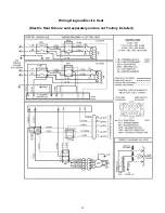
Page 12: ...Wiring Diagram Electric Heat Electric Heat Kits are sold separately and are not Factory Installed 12 ...

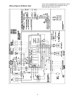
Page 13: ...Wiring Diagram Hot Water Heat If your unit is equipped with a multi function control board then for electric heat installations insure that heat selector pin is set to E 13 ...

Page 14: ...eat Allow up to 5 minutes for all sequencers to cycle off Check Change Airflow For proper cooling operation the airflow through the indoor coil should be between 350 and 450 CFM per ton of cooling capacity or 350 450 CFM per 12 000 BTU HR based on the rating of the outdoor unit The cooling blower speed is factory configured to provide correct airflow for an outdoor unit that matches the maximum co...

Page 15: ...ck wire High running from the blower motor to the control board 4 Remove this black wire from the control board and cover this loose end of this wire now with an insulating cap 5 Locate the Blue or Red wires connected to the blower motor Connect the Blue Med to the control board at its respective terminal for medium speed or connect the Red Low to the control board at its respective terminal for l...

Page 16: ...08 646 High 904 836 801 740 681 12 Low 1198 1144 1086 1018 962 Med 1257 1198 1130 1072 1010 High 1273 1215 1158 1094 1018 16 Low 1576 1514 1433 1338 1264 Med 1643 1576 1490 1407 1320 High 1707 1606 1545 1441 1364 20 Low 1759 1691 1652 1580 1512 Med 1838 1788 1729 1644 1555 High 1928 1867 1810 1729 1637 Speeds marked in bold with an asterisk are the factory speed settings for both heating and cooli...

Page 17: ...t room thermostat Circuit R W1 energizes a heat sequencer The completed circuit will energize supplemental electric heat if applicable Units with a second heater sequencer can be connected with the first sequencer to W1 on the thermostat or connected to a second heating stage W2 on the thermostat sub base Air Handler blower turns off 30 seconds after the thermostat stops calling for heating Emerge...

Page 18: ...tch A similar 24 V dry switching relay labeled TT can be used to activate a boiler or water heater valve After the circuit between R W are completed 1 Units with Factory Installed Aquastats The water temperature inside the hot water coil must reach 130 deg F before the circuit between R and G are complete activating the indoor blower motor To deactivate a factory installed aquastat simply move the...

Page 19: ...anty is void if the ADP product is removed from the original installation site This warranty does not apply to damage caused by shipping misuse mishandling or damage caused by floods winds fires lightning or exposure to corrosive elements environments such as salt chlorine fluorine or other damaging chemicals Limitations of Warranty The costs of refrigerant refrigerant reclamation miscellaneous ma...

Page 20: ......

Reviews: