Complete Installation
NOTE:
Refer to outdoor unit installation instructions for system
start-up instructions and refrigerant charging instructions.
PRE-Start Check
•
Is unit properly located, secure, and serviceable?
Does the MX Series Air Handler and Evaporator Coil
exhibit a ¾” pitch in the horizontal position towards the
drain pan to ensure proper condensate drainage?
•
Has an auxiliary pan been provided under the unit with
separate drain for units installed above a finished
ceiling or in any installation where condensate
overflows could cause damage?
•
Have all webs been removed from the drain
connections that are being used? Have all drain pan
plugs not used been properly plugged?
•
Has the condensate line been properly sized, run,
trapped, pitched, and tested?
•
Is the ductwork correctly sized, run, taped, and
insulated?
•
Have all cabinet openings and wiring been sealed?
•
Is the indoor coil orifice size correct?
•
Have all unused orifice replacement parts and
packaging been disposed of or recycled?
•
Is the filter clean, in place, and of adequate size?
•
Is the wiring neat, correct, and in accordance with the
wiring diagram?
•
Is the unit properly grounded and protected (fused)?
•
Is the thermostat correctly wired and in a good
location?
•
Are all access panels in place and secure?
Check Blower Operation
1. Set the thermostat to FAN ON.
2. The indoor blower should come on.
Check Electric Heater (if used)
1. Set thermostat to call for auxiliary heat (approximately
5
0
F above ambient temperature). The indoor blower
and auxiliary heat should come on together. Allow a
minimum of 3 minutes for all sequencers to cycle on.
2. Set the thermostat so it does not call for heat. Allow up
to 5 minutes for all sequencers to cycle off.
Check/Change Airflow
•
For proper cooling operation, the airflow through the
indoor coil should be between 350 and 450 CFM per
ton of cooling capacity (or 350 – 450 CFM per 12,000
BTU/HR) based on the rating of the outdoor unit.
•
The cooling blower speed is factory configured to
provide correct airflow for an outdoor unit that matches
the maximum cooling capacity rating of the MX Series
Air Handler.
•
If the outdoor unit is smaller than the maximum cooling
capacity rating for the MX Series Air Handler, the
cooling blower speed may need to be changed. Refer
to Blower Performance Chart.
IMPORTANT:
The cooling blower speed must be set to provide
a minimum of 350 CFM airflow per ton (12,000 BTU//HR) of
outdoor cooling capacity.
MAXIMUM KW FOR UNITS WITH NOMINAL
CFM SET AT 1400 (3.5 TONS) IS 15 KW.
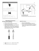
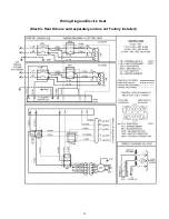
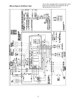
To change blower speed: Refer to “Wiring Diagram – Electric
Heat” or “Wiring Diagram – Hot Water Heat,” depending on
which application is being used.
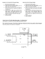
Models with 208/240 V, 60 Hz Supply Voltage
1.
Disconnect all power supplies
2.
Remove the MX Series Air Handler access panel.
3.
Locate pin number 2 on the blower relay. Two black
wires are connected to this terminal pin. One connects
to pin number 5 on the blower relay; one connects to
an inline splice connecting to a red or blue wire.
4.
Remove the wire going to the 4-pin blower motor
connector from the splice.
5.
Connect the blower lead (Red (LO), Black (HI)) onto
the splice from the 4-pin blower motor connector.
NOTE: Unused blower speeds are shipped
from the factory covered with a plastic cap.
Remove this cap from the new blower speed
terminal and replace it over the factory – set blower
terminal.
6.
Replace all panels and reconnect power.
NOTE: IF NOMINAL CFM IS SET AT
1000 (2.5 TONS) WITH 15 KW
ELECTRIC HEAT, THE MOTOR SPEED
MUST BE SET AT MEDIUM OR HIGHER.
14
Summary of Contents for MX Series
Page 20: ......

