Call StormTech at
860.529.8188
or
888.892.2694
or visit our website at
www.stormtech.com
for technical and product information.
25
7.0 Inletting the Chambers
7.6 OTHER INLET OPTIONS
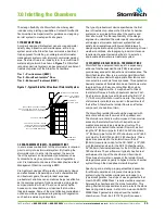
While the three-tiered treatment train approach is the
recommended method of inletting StormTech chambers
for typical under-commercial parking applications, there
are other effective inlet methods that may be considered.
For instance, Isolator Rows, while adding an inexpensive
level of confidence, are not always necessary. A header
system with fewer inlets can be designed to further
minimize the cost of a StormTech system. There may be
applications where stormwater pre-treatment may not
be necessary at all and the system can be inlet directly
from the source. Contact StormTech’s Technical Service
Department to discuss inlet options.
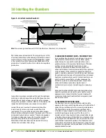
7.7 LATERAL FLOW RATES
The embedment stone surrounding the StormTech
chambers allows the rapid conveyance of stormwater
between chamber rows. Stormwater will rise and fall
evenly within a bed of chambers. A single StormTech SC-
740 chamber is able to release or accept stormwater at a
rate of at least 0.5 cfs (14.2 l/s) through the surrounding
stone.
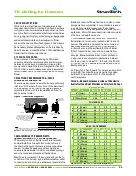
7.8 INLETTING PERPENDICULAR TO A ROW OF
CHAMBERS WITH INSERTA TEE
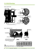
There is an easy, inexpensive method to perpendicularly
inlet a row of chambers. Simply connect the inlet directly
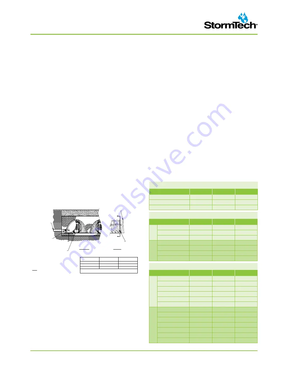
to the chamber with an Inserta Tee. Figure 9 shows a
typical detail along with the standard sizes offered for
each chamber model.
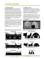
Figure 9 – Inserta Tee Side Detail
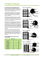
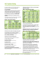
Table 9A – Standard Distances from Base of Chamber to
Invert of Inlet and Outlet Manifolds on StormTech End Caps
7.9 MAXIMUM INLET PIPE VELOCITIES TO
PREVENT SCOURING OF THE STONE FOUNDATION
The primary function of the inlet manifold is to convey
and distribute flows to a sufficient number of rows in
the chamber bed such that there is ample conveyance
capacity to pass the peak flows without creating an
unacceptable backwater condition in upstream piping or
scour the foundation stone under the chambers.
Manifolds are connected to the end caps either at the top
or bottom of the end cap. High inlet flow rates from either
connection location produce a shear scour potential of the
NOTE:
SIDe I
NSERTA TEES CANNOT BE USED ON SC-160LP CHAMBERS.
*See StormTech’s Tech Sheet #7 for manifold sizing guidance*
foundation stone. Inlet flows from top inlets also produce
impingement scour potential. Scour potential is reduced
when standing water is present over the foundation
stone. However, for safe design across the wide range of
applications, StormTech assumes minimal standing water
at the time the design flow occurs.
To minimize scour potential, StormTech recommends
the installation of woven scour protection fabric at each
inlet row. This enables a protected transition zone from
the concentrated flow coming out of the inlet pipe to
a uniform flow across the entire width of the chamber
for both top and bottom connections. Allowable flow
rates for design are dependent upon: the elevation of
inlet pipe, foundation stone size and scour protection.
An appropriate scour protection geotextile is installed
from the end cap to at least 10.5’ (3.2 m) for the SC-310,
SC- 740 and DC 780 chambers for both top and bottom
feeding inlet pipes.
See StormTech’s Tech Sheet #7 for guidance on manifold
sizing. ADS’s Technical Services department can also
assist with sizing inlet manifolds for the StormTech
chamber systems.
SC-310 END CAPS
PIPE DIA.
INV. (IN)
INV. (FT)
INV. (MM)
TOP
6” (150 mm)
5.8
0.48
146
8” (200 mm)
3.5
0.29
88
10” (250 mm)
1.4
0.12
37
BO
TTOM
6” (150 mm)
0.5
0.04
12
8” (200 mm)
0.6
0.05
15
10” (250 mm)
0.7
0.06
18
12” (750 mm)
0.9
0.08
24
SC-160LP END CAPS
PIPE DIA.
INV. (IN)
INV. (FT)
INV. (MM)
6" (150mm)
0.66
0.05
16
8" (200mm)
0.80
0.07
20
8" (200mm) Cored
0.96
0.08
24
SC-740 / DC-780 ENDCAPS
PIPE DIA.
INV. (IN)
INV. (FT)
INV. (MM)
TOP
6” (150 mm)
18.5
1.54
469
8” (200 mm)
16.5
1.38
421
10” (250 mm)
14.5
1.21
369
12” (300 mm)
12.5
1.04
317
15” (375 mm)
9
0.75
229
18” (450 mm)
5
0.42
128
BO
TTOM
6” (150 mm)
0.5
0.04
12
8” (200 mm)
0.6
0.05
15
10” (250 mm)
0.7
0.06
18
12” (750 mm)
1.2
0.10
30
15” (900 mm)
1.3
0.11
34
18” (1050 mm)
1.6
0.13
40
24” (1200 mm)
0.1
0.01
3
INSERTA TEE DETAIL
NTS
INSERTA TEE
CONNECTION
CONVEYANCE PIPE
MATERIAL MAY VARY
(PVC, HDPE, ETC.)
PLACE ADS GEOSYNTHETICS 315 WOVEN
GEOTEXTILE (CENTERED ON INSERTA-TEE
INLET) OVER BEDDING STONE FOR SCOUR
PROTECTION AT SIDE INLET CONNECTIONS.
GEOTEXTILE MUST EXTEND 6" (150 mm)
PAST CHAMBER FOOT
INSERTA TEE TO BE
INSTALLED, CENTERED
OVER CORRUGATION
SIDE VIEW
SECTION A-A
A
A
DO NOT INSTALL
INSERTA-TEE AT
CHAMBER JOINTS
NOTE:
PART NUMBERS WILL VARY BASED ON INLET PIPE MATERIALS.
CONTACT STORMTECH FOR MORE INFORMATION.
CHAMBER
MAX DIAMETER OF
INSERTA TEE
HEIGHT FROM BASE OF
CHAMBER (X)
SC-310
6" (150 mm)
4" (100 mm)
SC-740
10" (250 mm)
4" (100 mm)
DC-780
10" (250 mm)
4" (100 mm)
INSERTA TEE FITTINGS AVAILABLE FOR SDR 26, SDR 35, SCH 40 IPS
GASKETED & SOLVENT WELD, N-12, HP STORM, C-900 OR DUCTILE IRON
(X)
Summary of Contents for StormTech DC-780
Page 2: ...An company TOOL 2 0 DESIGN ...
Page 39: ......

