background image

Call StormTech at 

860.529.8188

 or 

888.892.2694

 or visit our website at 

www.stormtech.com

 for technical and product information.

3

2.0 Product Information

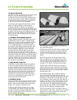
2.1 PRODUCT APPLICATIONS

StormTech chamber systems may function as stormwater 
detention, retention, first-flush storage, or some 
combination of these. The StormTech chambers can be 
used for commercial, municipal, industrial, recreational, 

and residential applications especially for installations 
under parking lots and commercial roadways.

One of the key advantages of the StormTech chamber 
system is its design flexibility. Chambers may be 
configured into beds or trenches of various sizes or 
shapes. They can be centralized or decentralized, and fit 
on nearly all sites. Chamber lengths enhance the ability to 
develop on both existing and pre-developed projects. The 
systems can be designed easily and efficiently around 
utilities, natural or man-made structures and any other 
limiting boundaries.

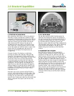
2.2 CHAMBERS FOR STORMWATER DETENTION

Chamber systems have been used effectively for storm 
water detention for over 15 years. A detention system 
temporarily holds water while it is released at a defined 
rate through an outlet. While some infiltration may 
occur in a detention system, it is often considered an 
environmental benefit and a storage safety factor. Over 
70% of StormTech’s installations are non-watertight 

detention systems. There are only a few uncommon 
situations where a detention system might need to 

limit infiltration: the subgrade soil’s bearing capacity is 
significantly affected by saturation such as with expansive 
clays or karst soils, and; in sensitive aquifer areas where 

the depth to groundwater does not meet local guidelines. 

Adequate pretreatment could eliminate concerns for the 
latter case. A thermoplastic liner may be considered for 
both situations to limit infiltration.

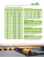
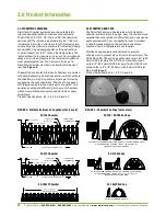
2.3 STONE POROSITY ASSUMPTION

A StormTech chamber system requires the application 
of clean, crushed, angular stone below, between and 
above the chambers. This stone serves as a structural 

component while allowing conveyance and storage of 

stormwater. Storage volume examples throughout this 

Design Manual are calculated with an assumption that 

the stone has an industry standard porosity of 40%. 

Actual stone porosity may vary. Contact StormTech for 
information on calculating storm water volumes with 
varying stone porosity assumptions.

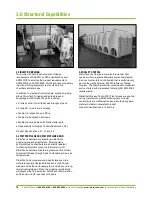
2.4 CHAMBER SELECTION

Primary considerations when selecting between the SC-
160LP, SC-310, SC-740 and DC-780 chambers are the 
depth to restrictive layer, available area for subsurface 
storage, cover height and outfall restrictions.

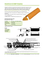
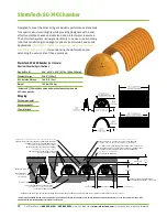
The StormTech SC-160LP chamber shown on page 
4 is the smallest of the chamber family and has been 
optimized to fit in the shallowest of applications. This 
extra low profile chamber allows for storage of 1.01 ft

3

/ft

2


(0.3m

3

/m

2

) [minimum] of storage.

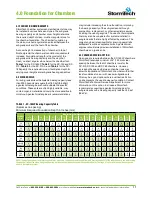
The SC-310 and SC-740 chambers and end plates.

StormTech systems can be integrated into retrofit and 
new construction projects.

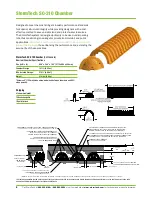
The StormTech SC-310 chamber shown on page 6 is ideal 
for systems requiring low-rise and wide-span solutions. 
This low profile chamber allows the storage of large 
volumes, 1.3 ft

3

/ft

2

 (0.40 m

3

/m

2

) [minimum], at minimum 

depths. 

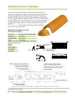
Like the Stormtech SC-310, the StormTech SC-310-
3 found on page 8 allows for a design option for sites 
with both limited cover and limited space. With only 3” 
of spacing between the chambers, the SC-310-3 still 

provides 1.3 ft

3

/ft

2

 (0.40 m

3

/m

2

) [minimum] of storage.

The StormTech SC-740 chamber shown on page 10 

optimizes storage volumes in relatively small footprints. 

By providing 2.2 ft

3

/ft

2

 (0.67 m

3

/m

2

) [minimum] of storage, 

the SC-740 chambers can minimize excavation, backfill 

and associated costs.

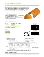
The DC-780 chamber shown on page 12 has been 
developed for those applications which exceed the 
maximum 8 ft (2.44 m) burial depth of the SC-740 and SC-
310 chambers. The DC-780 is a modified version of the 
SC-740 allowing it to reach a maximum burial depth of 12 
ft (3.66 m). The design of the DC-780 chamber, like other 
StormTech chambers, is designed and manufactured 
in accordance with the AASHTO LRFD Bridge Design 
Specifications as well as ASTM F 2418 and ASTM F 2787 
ensuring structural adequacy for deeper systems.

The end corrugations of the DC-780 chamber have not 
been modified in order to allow connections to the SC-740 
chamber. This will allow hybrid systems utilizing both 
chambers in one system design. 

Summary of Contents for StormTech DC-780

Page 1: ...isit our website at www stormtech com for technical and product information 1 StormTech MC 3500 Chamber SC 160LP SC 310 SC 740 DC 780 Design Manual THE MOST ADVANCED NAME IN WATER MANAGEMENT SOLUTIONS StormTech Chamber Systems for Stormwater Management ...

Page 2: ...An company TOOL 2 0 DESIGN ...

Page 3: ...igns please refer to the MC 3500 MC 4500 Design Manual The StormTech Technical Services Department assists design professionals in specifying StormTech storm water systems This assistance includes the layout of chambers to meet the engineer s volume requirements and the connections to and from the chambers The Technical Department can also assist converting and cost engineering projects currently ...

Page 4: ...nts of Section 12 12 of the AASHTO LRFD Bridge Design Specifications and produced to the requirements of the American Society of Testing Materials ASTM International specifications F2418 polypropylene chambers and F2922 polyethylene chambers StormTech chambers provide the full AASHTO safety factors for live loads and permanent earth loads The two ASTM standards mentioned previously are linked to t...

Page 5: ... volume examples throughout this Design Manual are calculated with an assumption that the stone has an industry standard porosity of 40 Actual stone porosity may vary Contact StormTech for information on calculating storm water volumes with varying stone porosity assumptions 2 4 CHAMBER SELECTION Primary considerations when selecting between the SC 160LP SC 310 SC 740 and DC 780 chambers are the d...

Page 6: ...ONSIBLE FOR THE ENSURING THE REQUIRED BEARING CAPACITY OF SUBGRADE SOILS PAVEMENT LAYER DESIGNED BY SITE DESIGN ENGINEER CHAMBERS SHALL BE BE DESIGNED IN ACCORDANCE WITH ASTM F2787 STANDARD PRACTICE FOR STRUCTURAL DESIGN OF THERMOPLASTIC CORRUGATED WALL STORMWATER COLLECTION CHAMBERS GRANULAR WELL GRADED SOIL AGGREGATE MIXTURES 35 FINES COMPACT IN 6 150 mm MAX LIFTS TO 95 PROCTOR DENSITY SEE THE T...

Page 7: ... 0 168 9 49 0 269 11 279 5 40 0 153 8 67 0 246 10 254 4 78 0 135 7 81 0 221 9 229 4 10 0 116 6 91 0 196 8 203 3 36 0 095 5 97 0 169 7 178 2 58 0 073 5 01 0 142 6 152 1 76 0 050 4 02 0 114 5 127 0 89 0 025 3 01 0 085 4 102 0 0 1 98 0 056 3 76 0 0 1 48 0 042 2 51 0 0 0 99 0 028 1 25 0 0 0 49 0 014 Stone Foundation Stone Cover ENGLISH TONS yds3 Stone Foundation Depth 4 6 8 StormTech SC 160LP 1 1 0 8 ...

Page 8: ...TO 24 600 mm SITE DESIGN ENGINEER IS RESPONSIBLE FOR THE ENSURING THE REQUIRED BEARING CAPACITY OF SUBGRADE SOILS PAVEMENT LAYER DESIGNED BY SITE DESIGN ENGINEER CHAMBERS SHALL BE BE DESIGNED IN ACCORDANCE WITH ASTM F2787 STANDARD PRACTICE FOR STRUCTURAL DESIGN OF THERMOPLASTIC CORRUGATED WALL STORMWATER COLLECTION CHAMBERS GRANULAR WELL GRADED SOIL AGGREGATE MIXTURES 35 FINES COMPACT IN 6 150 mm ...

Page 9: ... as the depth of the cover increases Volume Excavation Per Chamber yd3 m3 Note Assumes 6 150 mm of stone above chambers 6 150 mm row spacing and 40 stone porosity Depth of Water in System Inches mm Cumulative Chamber Storage ft3 m3 Total System Cumulative Storage ft3 m3 28 711 14 70 0 416 31 00 0 878 27 686 14 70 0 416 30 21 0 855 26 680 14 70 0 416 29 42 0 833 25 610 14 70 0 416 28 63 0 811 24 60...

Page 10: ...ARING CAPACITY OF SUBGRADE SOILS PAVEMENT LAYER DESIGNED BY SITE DESIGN ENGINEER CHAMBERS SHALL BE BE DESIGNED IN ACCORDANCE WITH ASTM F2787 STANDARD PRACTICE FOR STRUCTURAL DESIGN OF THERMOPLASTIC CORRUGATED WALL STORMWATER COLLECTION CHAMBERS GRANULAR WELL GRADED SOIL AGGREGATE MIXTURES 35 FINES COMPACT IN 6 150 mm MAX LIFTS TO 95 PROCTOR DENSITY SEE THE TABLE OF ACCEPTABLE FILL MATERIALS ADS GE...

Page 11: ... 39 0 124 5 127 0 0 3 66 0 104 4 102 0 0 2 93 0 083 3 76 0 0 2 19 0 062 2 51 0 0 1 46 0 041 1 25 0 0 0 73 0 021 Stone Foundation Stone Cover ENGLISH TONS yds3 Stone Foundation Depth 6 12 16 SC 310 3 1 9 1 4 2 5 1 8 3 1 2 2 METRIC KILOGRAMS m3 150 mm 300 mm 450 mm SC 310 3 1 724 1 0 2 268 1 3 2 812 1 7 Note Assumes 6 150 mm of stone above and and 3 76 mm row spacing Amount of Stone Per Chamber Ston...

Page 12: ...TH ASTM F2787 STANDARD PRACTICE FOR STRUCTURAL DESIGN OF THERMOPLASTIC CORRUGATED WALL STORMWATER COLLECTION CHAMBERS GRANULAR WELL GRADED SOIL AGGREGATE MIXTURES 35 FINES COMPACT IN 6 150 mm MAX LIFTS TO 95 PROCTOR DENSITY SEE THE TABLE OF ACCEPTABLE FILL MATERIALS ADS GEOSYTHETICS 601T NON WOVEN GEOTEXTILE ALL AROUND CLEAN CRUSHED ANGULAR EMBEDMENT STONE CHAMBERS SHALL MEET THE REQUIREMENTS FOR ...

Page 13: ...12 305 12 97 0 367 21 31 0 608 11 279 10 87 0 309 18 92 0 535 10 254 8 74 0 247 16 51 0 468 9 229 6 58 0 186 14 09 0 399 8 203 4 41 0 125 11 66 0 330 7 178 2 21 0 063 9 21 0 264 6 152 0 0 6 76 0 191 5 127 0 0 5 63 0 160 4 102 0 0 4 51 0 128 3 76 0 0 3 38 0 096 2 51 0 0 2 25 0 064 1 25 0 0 1 13 0 032 Stone Foundation Stone Cover ENGLISH TONS yds3 Stone Foundation Depth 6 12 16 SC 740 3 8 2 8 4 6 3 ...

Page 14: ...S GRANULAR WELL GRADED SOIL AGGREGATE MIXTURES 35 FINES COMPACT IN 6 150 mm MAX LIFTS TO 95 PROCTOR DENSITY SEE THE TABLE OF ACCEPTABLE FILL MATERIALS ADS GEOSYTHETICS 601T NON WOVEN GEOTEXTILE ALL AROUND CLEAN CRUSHED ANGULAR EMBEDMENT STONE CHAMBERS SHALL MEET ASTM F2418 STANDARD SPECIFICATION FOR POLYPROPLENE PP CORRUGATED WALL STORMWATER COLLECTION CHAMBERS EMBEDMENT STONE SHALL BE A CLEAN CRU...

Page 15: ...6 27 1 310 77 34 2 190 43 1 092 46 27 1 310 76 21 2 158 42 1 067 46 27 1 310 75 09 2 126 41 1 041 46 27 1 310 73 96 2 094 40 1 016 46 27 1 310 72 83 2 062 39 991 46 27 1 310 71 71 2 030 38 965 46 21 1 309 70 54 1 998 37 940 46 04 1 304 69 32 1 963 36 914 45 76 1 296 68 02 1 926 35 889 45 15 1 278 66 53 1 884 34 864 44 34 1 255 64 91 1 838 33 838 43 38 1 228 63 21 1 790 32 813 42 29 1 198 61 43 1 7...

Page 16: ...pletes the row The trimmed off piece of a StormTech chamber may then be used to start the next row See Figure 4 To assist the contractor StormTech chambers are molded with simple assembly instructions and arrows that indicate the direction in which to build rows Rows are formed by overlapping the next chamber s Start End corrugation with the previously laid chamber s end corrugation Two people can...

Page 17: ...ch products underneath buildings or parking garages When specifying the StormTech products in close proximity to buildings it is important to ensure that the StormTech products are not receiving any loads from these structures that may jeopardize the long term performance of the chambers 3 2 FULL SCALE TESTING After developing the StormTech chamber designs the chambers were subjected to rigorous f...

Page 18: ...pylene and polyethylene Polypropylene and polyethylene chambers are inherently resistant to chemicals typically found in stormwater run off StormTech chambers maintain a greater portion of their structural stiffness through higher installation and service temperatures StormTech polypropylene and polyethylene are virgin materials specially designed to achieve a high 75 year creep modulus that is ne...

Page 19: ...required between the SC 160LP chambers StormTech requires a minimum of 6 150 mm clear spacing between the feet of chambers rows for the SC 310 SC 740 and DC 780 chambers However increasing the spacing between chamber rows may allow the application of StormTech chambers with either less foundation stone or with weaker subgrade soils This may be a good option where a vertical restriction on site pre...

Page 20: ...30 9 230 9 230 9 230 9 230 12 300 12 300 12 300 12 300 15 375 15 375 18 450 18 450 21 550 5 0 1 52 6 150 6 150 6 150 6 150 6 150 6 150 6 150 6 150 9 230 9 230 9 230 9 230 9 230 12 300 12 300 12 300 15 375 15 375 15 375 18 450 18 450 21 550 5 5 1 68 6 150 6 150 6 150 6 150 6 150 6 150 6 150 9 230 9 230 9 230 9 230 9 230 12 300 12 300 12 300 12 300 15 375 15 375 15 375 18 450 18 450 21 550 6 0 1 83 ...

Page 21: ...ble for assessing the bearing resistance allowable bearing capacity of the subgrade soils and determining the depth of foundation stone Subgrade bearing resistance should be assessed with consideration for the range of soil moisture conditions expected under a stormwater system TABLE 3 SC 310 3 Minimum Required Foundation Depth in inches millimeters Cover Hgt ft m Minimum Required Bearing Resistan...

Page 22: ...14 22 0 403 23 58 0 668 18 457 13 68 0 387 22 47 0 636 17 432 12 99 0 368 21 25 0 602 16 406 12 17 0 345 19 97 0 566 15 381 11 25 0 319 18 62 0 528 14 356 10 23 0 290 17 22 0 488 13 330 9 15 0 260 15 78 0 447 12 305 7 99 0 227 14 29 0 425 11 279 6 78 0 192 12 77 0 362 10 254 5 51 0 156 11 22 0 318 9 229 4 19 0 119 9 64 0 278 8 203 2 83 0 081 8 03 0 227 7 178 1 43 0 041 6 40 0 181 6 152 0 4 74 0 13...

Page 23: ...14 09 0 399 8 203 4 41 0 125 11 66 0 330 7 178 2 21 0 063 9 21 0 264 6 152 0 6 76 0 191 5 127 0 5 63 0 160 4 102 0 4 51 0 125 3 76 0 3 38 0 095 2 51 0 2 25 0 064 1 25 0 1 13 0 032 Depth of Water in System Inches mm Cumulative Chamber Storage ft3 m3 Total System Cumulative Storage ft3 m3 45 1143 46 27 1 310 78 47 2 222 44 1118 46 27 1 310 77 34 2 190 43 1092 46 27 1 310 76 21 2 158 42 1067 46 27 1 ...

Page 24: ...Engineer s plans Check plans for pavement subgrade requirements N A Prepare per site design Engineer s plans Paved installations may have stringent material and preparation requirements C Initial Fill Fill material for layer C starts form the top of the embedment stone B Layer to 18 450 mm above the top of the chamber Note that pavement subbase may be a part of the C layer Granular well graded soi...

Page 25: ...t an appropriate stormwater pre treatment system 7 3 STORMTECH ISOLATOR ROW TREATMENT TIER 2 StormTech has a patented technique to inexpensively enhance Total Suspended Solids TSS removal and provide easy access for inspection and maintenance The StormTech Isolator Row is a row of standard StormTech chambers surrounded with appropriate filter fabrics and connected to a manhole for easy access This...

Page 26: ... works closely with providers of enhanced treatment technologies to meet local requirements 7 5 TREATMENT TRAIN CONCLUSION The treatment train is a highly effective water quality approach that may not add significant cost to a StormTech system being installed under commercial parking areas The StormTech Isolator Row adds a significant level of treatment easy inspection and maintenance while mainta...

Page 27: ...et flows from top inlets also produce impingement scour potential Scour potential is reduced when standing water is present over the foundation stone However for safe design across the wide range of applications StormTech assumes minimal standing water at the time the design flow occurs To minimize scour potential StormTech recommends the installation of woven scour protection fabric at each inlet...

Page 28: ... as shown in Figures 10 and 11 Solid outlet pipes should also be used to penetrate the StormTech end caps at the designed outlet invert as shown in Figure 12 An Isolator Row should not be directly penetrated with an outlet pipe For systems requiring higher outlet flow rates a combination of connections may be utilized as shown in Figure 13 In detention and retention applications the discharge of w...

Page 29: ...c Rows of chambers can be ended short or interrupted by placing an end cap at the desired location leaving the required number of chambers out of the row to get by the obstruction then starting the row of chambers again with another end cap See Figure 14 for an example 9 4 LINERS StormTech chambers offer the distinct advantage and versatility that allow them to be designed as an open bottom detent...

Page 30: ...g the bed configuration to fit a specific site call StormTech s Technical Services Department at 1 888 892 2694 1 Determine the amount of storage volume VS required It is the design engineer s sole responsibility to determine the storage volume required by local codes 2 Determine the number of chambers C required To calculate the number of chambers needed for adequate storage divide the storage vo...

Page 31: ... PORT DETAIL NTS CONCRETE SLAB 8 200 mm MIN THICKNESS THE PART 2712AG6IPKIT CAN BE USED TO ORDER ALL NECESSARY COMPONENTS FOR A SOLID LID INSPECTION PORT INSTALLATION 6 150 mm INSERTA TEE PART 6P26FBSTIP INSERTA TEE TO BE CENTERED ON CORRUGATION CREST PAVEMENT CONCRETE COLLAR CONCRETE COLLAR NOT REQUIRED FOR UNPAVED APPLICATIONS 12 300 mm NYLOPLAST INLINE DRAIN BODY W SOLID HINGED COVER PART 2712A...

Page 32: ...N AT SIDE INLET CONNECTIONS GEOTEXTILE MUST EXTEND 6 150 mm PAST CHAMBER FOOT INSERTA TEE TO BE INSTALLED CENTERED OVER CORRUGATION SIDE VIEW SECTION A A A A DO NOT INSTALL INSERTA TEE AT CHAMBER JOINTS NOTE PART NUMBERS WILL VARY BASED ON INLET PIPE MATERIALS CONTACT STORMTECH FOR MORE INFORMATION CHAMBER MAX DIAMETER OF INSERTA TEE HEIGHT FROM BASE OF CHAMBER X SC 310 6 150 mm 4 100 mm SC 740 10...

Page 33: ...t sediment from entering the system during construction it is during this time that excess amounts of sediments are most likely to enter any stormwater system Inspection and maintenance if necessary should be performed prior to passing responsibility over to the site s owner Once in normal service a StormTech Isolator Row should be inspected bi annually until an understanding of the sites characte...

Page 34: ... step 5 If not proceed to step 6 5 Vacuum pump the sediment Do not flush sediment out inlet pipes 6 Replace grates and covers 7 Record depth and date and schedule next inspection STORMTECH ISOLATOR ROW STEP BY STEP MAINTENANCE PROCEDURES Step 1 Inspect Isolator Row for sediment A Inspection ports if present i Remove lid from floor box frame ii Remove cap from inspection riser iii Using a flashligh...

Page 35: ... m including pavement design For installations that do not include pavement where rutting from vehicles may occur minimum required cover is 24 610 mm maximum cover is as stated above 4 The contractor must report any discrepancies with the bearing capacity of the chamber foundation materials to the design engineer 5 AASHTO M288 Class 2 non woven geotextile filter fabric must be used as indicated in...

Page 36: ...tion system StormTech chambers detain and allow for the metered flow of water to an outfall 2 0 CHAMBER PARAMETERS 2 1 The Chamber shall be injection molded of an impact modified polypropylene or polyethylene copolymer to maintain adequate stiffness through higher temperatures experienced during installation and service 2 2 The nominal chamber dimensions of the StormTech SC 740 and DC 780 shall be...

Page 37: ...d end caps shall be produced at an iso 9001 certified manufacturing facility SC 160LP STORMTECH CHAMBER SPECIFICATIONS 1 Chambers shall be Stormtech SC 160LP 2 Chambers shall be arch shaped and shall be manufactured from virgin impact modified polypropylene copolymers 3 Chambers shall meet the requirements of ASTM F2418 16A Standard Specification for Polypropylene PP Corrugated Wall Stormwater Col...

Page 38: ...erformance Chambers and end caps shall be produced at an iso 9001 certified manufacturing facility SC 740 STORMTECH CHAMBER SPECIFICATIONS 1 Chambers shall be Stormtech SC 740 2 Chambers shall be arch shaped and shall be manufactured from virgin impact modified polypropylene copolymers 3 Chambers shall meet the requirements of ASTM F2418 16A Standard Specification for Polypropylene PP Corrugated W...

Page 39: ......

Page 40: ... of the art products and services that meet or exceed industry performance standards and expectations We offer designers regulators owners and contractors the highest quality products and services for stormwater management that Saves Valuable Land and Protects Water Resources MC 3500 and MC 4500 Chambers and End Caps SC 160LP SC 310 and SC 740 Chambers End Caps DC 780 Chambers and End Caps Fabrica...

Reviews: