
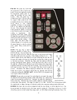


most applications the normal force range is adequate (see Dynamic Force Adjust (Advanced
Option) and high resolution force mode in the Remote Panel section). In the normal force range
mode, the force is adjustable between 10 and 550 grams of force in 100 steps. On the 315/230
front panel rotate the force knob to change the force. In the cas position the computer settings
control the force.
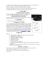
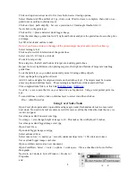
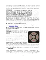
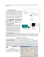
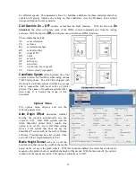
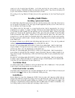
The force is set by test cutting the media to be cut using the test cut
function. Using the joystick, position the knife in an unused portion of the
media and press the
TEST CUT
key. The system will cut a test cut
pattern similar to the diagram to the right. With a sharp knife or tweezers
you should be able to individually remove each part of the test cut pattern
working from the ring to the triangle without affecting the remaining parts.
A properly set force will leave a very slight scratch or mark on the liner.
The force may need to be adjusted due to blade wear during use if problems with weeding occur.
Simply increase the force setting by one until satisfactory weeding occurs. If the knife blade is
changed, revert back to the original setting or perform the test cut procedure again. The blade may
need to be replaced if the force is increased by more than 20 percent from when the blade was new.
The remainder of this section does not apply to 230/315 models.
F1
This key puts the pen up or down during digitizing mode.
F2
activates the F2 -> copy function. This is used to perform Smartmark
TM
operations on identical
F3
This key is a short cut to the OPER mode. It is equivalent to pressing select, left/right until
OPEr is displayed and pressing select.
RESET
the cutter by pressing the F1, F2 and F3 keys in order.
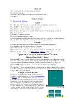
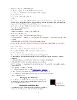
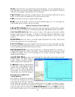
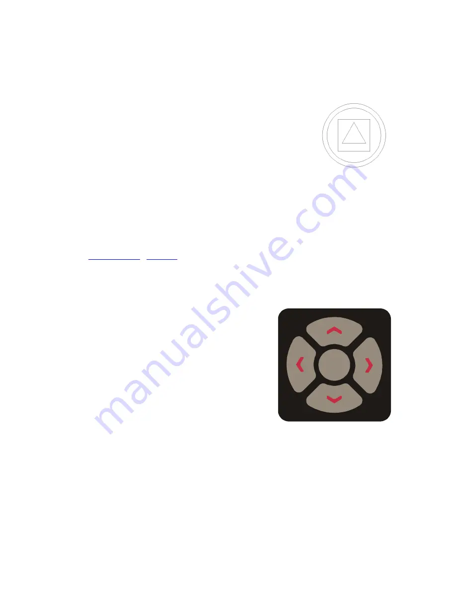
JOYSTICK
The joystick is used for positioning the knife
and media in the die cutting station and for several other
functions.
The four
ARROW KEYS
are used to jog the material or
cutter carriage that holds the knife blade and the SmartMark
sensor. Press the key once to move the material or carriage
slowly and press it a second time within ½ second to move at
a faster speed. Tap the key to jog the cutter a fixed distance.
The distance is adjustable (see Joy section below or joystick in
the Remote Panel section).
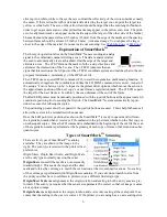
SELECT
The select key is used to invoke the menu system.
Press the select key and the display will change to indicate the
last used menu item. To select a menu item press the select key and then press the right or left
arrow key to scroll thru the various menu items. With the desired menu item displayed, press the
up or down arrow key to select the state. When the desired state is displayed press the select key to
input the menu item and state. The menu items are: ACCL, CAd, diA, indE, JOY, OPEr, and Set.
Menu Items:
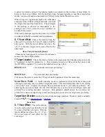
ACCL
allows setting the acceleration in ¼ G increments. Acceleration is the rate of
increase/decrease of speed of the motors along a vector. Higher G values increase throughput
however higher G values also increase the likelihood of experiencing repeatability problems.
Recommended values are (1-8) for standard media. Use lower values for heavy media.
12
SELECT


