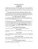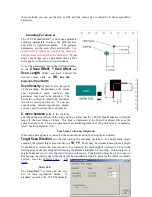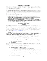
5. Verify belt path and tension.
6. Replace the control panel housing, top rail cover and rear cover.
X-Axis
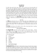
The belt inside the rear cover drives the grit wheel (X axis). To adjust the tension of this belt, it is
necessary to reposition the motor.
1. Loosen the two motor bracket screws and apply hand pressure to tighten the belt so
that the belt will deflect 1/16 inch at the center when 23 ounces are applied. (2 mm
when 660 grams are applied). (Replace belt if damaged or worn).
2. When the belt is correctly tensioned, tighten the two motor bracket screws.
3. Verify belt path and tension. Check that the large gear turns freely.
Diagnostics
The i-TECH CUTTER firmware contains a set of resident diagnostics. When the i-TECH
CUTTER is powered up, it automatically performs a self-test program to check all operating
parameters. If a malfunction is detected, the letter “E” and a three-digit error number will be
displayed in the display window. The error numbers and the corresponding malfunction
descriptions are given in the Error Codes section. When an error is displayed and no obvious
damage was done to the cutter, power off the cutter and repeat the procedure that caused the error
display. If the error reoccurs, the user may push any key on the control panel to enter the diagnostic
mode. Many errors automatically place the cutter in the diagnostic mode when a key is pressed.
The fail-safe system is designed to detect failures in the operation of the electromechanical system
in the cutter and to prevent such failures from causing other damage. The cutter monitors motor
currents and will generate an error if motor current too high or unmeasureable. It also generates an
error for impossible or dangerous conditions. The appropriate error code will appear, as mentioned
above, in the display window on the control panel.
Diagnostic Operation
The diagnostics in the i-TECH Cutter exist at several levels:
a. POWER-ON
b. CONTINUOUS HARDWARE AND SOFTWARE MONITORING
c. OFF-LINE
The POWER-ON diagnostics are performed at power-on or reset of the microprocessor and test the
microprocessor, memory, servo analog and digital hardware, and some of the testable sensors.
After initialization, continuous hardware and software check the sensors and fail-safe monitors for
machine malfunctions. If a malfunction is detected, an error code is displayed on the control panel
display, the protection relay is opened, and the cutter ceases operation.
Control panel operation
Starting the diagnostics from Control Panel
Turn unit on and allow initialization to complete. If the i-TECH Cutter is displaying a flashing
error code on the front panel display, press any key to enter the diagnostic mode.
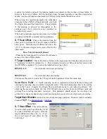
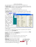
Press the select key to initiate the menu function, Press the left or right arrow key to display
diA
.
Press the up or down key to scroll thru the diagnostic numbers (0002 – 0099). Press the select key
to start the diagnostic.
29

