silver spot on white, while to the eye there is contrast the reflectivity of the two is sometimes nearly
the same. If there is trouble with certain materials detecting the target you can print the target in a
yellow or white field. The size of the yellow field should be larger than the scan length. (
Note:
in
order to get an accurate scan no other printed marks may appear in the yellow scan area. The print-
er color alignment marks can appear on the inside edge of the target or the other side of the media.)
The mark should be placed at least 0.5 inches (12 mm) from the edge of the media and the spacing
between frames should be at least 0.5 inch (12 mm). (Advanced usage: You can place the target
closer to the edge of the material if you use inside out scanning. See
Explanation of SmartMark
TM
The theory of operation relies on the SmartMark
sensor sending an analog
signal to the embedded computer during a scan. The data is analyzed after
the scan to automatically create a threshold, find the edge of the target and
eliminate noise. The i-TECH scans the mark in both x and y directions and
calculates the intersection of the 2 scans. The i-TECH computer then as-
signs that intersection as the 0,0 point of the i-TECH coordinate system and matches that to the ori-
gin point (minimum x, minimum y) of the HPGL cut file.
The i-TECH uses a special HPGL command, FO, to start the registration mark sensing function. It
automatically re-registers the coordinate each time the FO HPGL command is received. As part of
the setup a “x move between jobs” is input via the printer driver options which moves the sensor to
the approximate position of the next copy’s or next frame’s registration mark. The i-TECH expects
the target for the next frame to be within ½ the scan distance of the end of the frame.
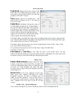
The Red LED pointer must be manually positioned with the joystick buttons at the approximate 0,0
coordinate position prior to sending the first job. The SmartMark
system automatically reposi-
tions the sensor for subsequent copies.
The positioning process must be repeated if the joystick buttons are used. This is helpful because it
allows the system to be reinitialized when needed.
Once the LED pointer is positioned as shown, the SmartMark
is ready to operate and will scan
the registration mark when it receives a FO command in the job stream whether on the first copy or
on subsequent copies. Since the FO command is embedded in the beginning of the cut file the scan
of the registration mark is performed at the beginning of each copy or frame of labels and on subse-
quent copies.
Types of SmartMark
TM
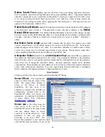
Scanning
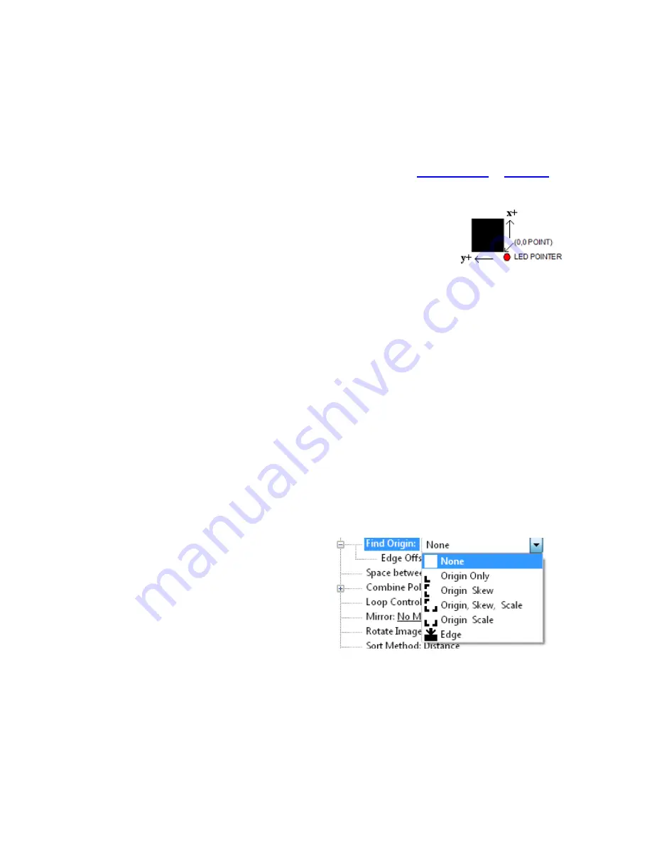
There are five types of SmartMark
TM
scanning
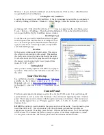
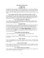
available. They are shown in the image to the
right. The scan type is selected in the printer driver
preferences.
Origin Skew, Origin Skew Scale, and Origin Scale
are the only types normally used on the cutter.
Origin Skew
is used if the media is not necessarily
loaded straight. This scans the origin and the skew
mark and rotates the cut image to match the cut location at the two scanned locations. No scaling
of the cut image is performed with Origin Skew scanning. If you cuts do not match in size from
the print you either have to calibrate to printer or use a different find origin type.
Origin Skew Scale
does alignment at the origin, rotation and scaling in both x and y axes are pre-
formed. This scan type requires that the sensor size parameter be correct so that cut image is same
size as printed image.
Origin Scale
does alignment at the origin, rotation and x-axis only scaling at the scale point. It as-
sumes that the scaling in the y-axis is correct. If the printer you are using has a x axis scaling error
6


