Pinch Wheel Maintenance
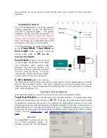
Pinch wheels are critical to the i-TECH unit's material handling performance. They should be
inspected for wear regularly and cleaned as needed. To clean adhesive off the pinch wheels, simply
use a soft cloth and denatured alcohol.
In normal use, the pinch wheels will need to be replaced in time. Also, trying to move them when
they are in the down position can damage them. If material does not track well and guide alignment
has been verified, the pinch wheels may need to be replaced. For best tracking results, replacement
pinch wheels should be replaced as a SET.
To check condition of pinch wheels:
1) Inspect condition of rubber
The rubber wheel should not have any cracks and should be
securely adhered to the aluminum hub of the wheel. The transition from the flat surface of the
wheel to the "sidewall" edges of the wheel should be sharp and not rounded.
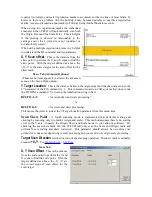
2) Inspect integrity of pinch wheel bearing
This is done by having the pinch wheels in the up
position. Spin wheel with finger and observe whether the bearing has a dry sound or not. If it
appears to be dry, the wheels should be replaced.
Mechanical Adjustments
Belt Tension
The i-TECH servomotors use timing belts to control the material (X axis) and tool (Y axis)
positions. The belt tension and wear should be inspected if cut quality deteriorates. To inspect the
belts, remove the pods at either end of the i-TECH. This can be done by removing about 16 screws
along the edge of the pod covers. You can operate the cutter with pods installed in the extended
position by reinstalling the pods using two screws. (see also TSB: Mechanical Adjustments to
Restore Cut Quality
Y-Axis
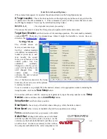
The Y-axis short belt runs between the Y-axis servomotor and a gear assembly under the left hand
pod. To adjust the tension of this belt, it is necessary to reposition the motor bracket.
1. Loosen the three Phillips head motor bracket screws and apply hand pressure to
tighten the belt so that the belt will deflect 0.050 inches at the center when 23
ounces are applied. (1.3 mm when 660 grams are applied).
2. When the belt is tight and the motor shaft is
parallel
to the bearing shaft, tighten
the three Phillips head motor bracket screws.
Premature belt failure will occur if
these two shafts are not parallel.
3. Verify tension.
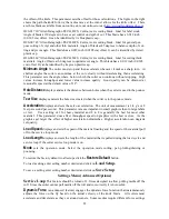
The long belt is adjusted using a lead screw located behind the control panel. To set the long belt's
tension:
1. Position the carriage to about 24 inches from one end.
2. Remove the control panel housing as follows
a. Install the right pod at extended position as described above.
b. Remove the top rail cover over the carriage by removing the two screws at
each end of the cover.
3. Loosen locking nut. Adjust the lead screw so that the 24" of belt when plucked like a
guitar string vibrates at a low base note. It should not flop around and stop oscillating
immediately.
4. Set the lead screw lock nut.
28


