background image

2


Chapter 3: ADT Pulse Enrollment


7


DBC835 Wireless Doorbell Camera Installation


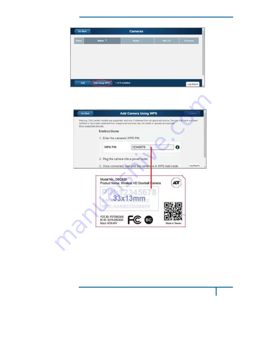
5. Click the Add Using WPS button at the bottom of the screen. 


Figure 5: Clicking "Add Using WPS" Button 

6. Locate the camera’s PIN number on the label on the rear of the 

camera. Enter the PIN number in the WPS PIN field. 


Figure 6: Entering the PIN 


Summary of Contents for DBC835

Page 1: ...CdbaADTS ASAPandth egistered ma e Inte DB s HD k Inst rmationaccu any kind SecurityServ heproduct s arks Unaut ractiv C835 Doorb tallatio urateasofpu vices Allrig servicenam thorized use ve Solu bell Ca onGu ublisheddat ghtsreserve meslistedint e is strictly p utions amera ide teandispro ed ADT the thisdocume rohibited s a vided ADT entare ...

Page 2: ... Mount Wood Scre Gang Box S ackage C D 1 uctio provides d and capabi items are Camera x 1 ting Bracke ew Anchor Screw x 2 Content DBC835 W n details of th lities included in ets Small x 2 ts Wireless Doo he Doorbell n the packa One gan orbell Came l Camera s age ng box size era Installat s features e ion 1 ...

Page 3: ...amera Installation DBC835 supports both analog and digital chime within AC 8 24 voltage The operation temperature is 4 F to 122 F 20 C to 50 C The battery will not be charged when the temperature is 0 C Figure 1 Front Panel Figure 2 Rear Panel Overview ...

Page 4: ...function is disabled 2 Doorbell Press the button to ring the bell LED Behavior z Off No power z On Blue Power On Network connection is available z Blinking Green The WPS connection is active z On Red If the LED is on for 5 seconds and then turns off the WPS function has failed z Blinking Red Network connection is failed z Spinning Green The firmware is being upgraded z Intermittent Blinking Red If...

Page 5: ...operation If you don t see the camera powering up please charge the doorbell camera via Micro USB cable with USB charger for 2 hours before installation Note 2 If the LED does not flash red please hold the reset button for 15 seconds to factory default the camera then start the installation process over Figure 3 Power LED 2 Enroll the Camera in ADT Pulse This process is described in Chapter 3 ADT ...

Page 6: ...wait for the LED turning flashing red as described in the previous chapter 2 Launch an Internet browser and log in to the Pulse portal or TS installer app 3 Enter the Manage Devices screen using one of these methods x For the Pulse portal select the System tab and click Manage Devices x For the TS installer app click the following Pulse Devices link https portal aries icontrol com myhome 9 6 0 323...

Page 7: ... Camera Installation 5 Click the Add Using WPS button at the bottom of the screen Figure 5 Clicking Add Using WPS Button 6 Locate the camera s PIN number on the label on the rear of the camera Enter the PIN number in the WPS PIN field Figure 6 Entering the PIN ...

Page 8: ...turned to blinking green for WPS process Note This WPS process must be completed within 2 minutes or else it will be time out The remaining time is displayed in the upper left portion of the screen 8 Click the Continue button to initiate the WPS process Figure 7 Clicking Continue Button Figure 8 Add Camera Using WPS Screen ...

Page 9: ... the Camera Details screen will be displayed Name the device and select the desired bandwidth chimer type Click Save after entering all the data Figure 9 Saving Camera Details 10 The newly added device will be shown in the Cameras list then click Go Back at the top left of the screen Figure 10 Clicking Go Back Button ...

Page 10: ...em page to check if the device is enrolled already Figure 12 System Screen 13 Move the camera to where the doorbell button is located and check the LED to see if the camera still has WiFi connectivity Note If the WiFi cannot reach the front doorbell camera you will see the power LED kept blinking red Then a repeater is required or move the CloudLink TSS to the center of the house ...

Page 11: ...breaker c F the legacy nded instal Fig n bell Camera nstalla tails for wa at the cam rmanently ircuit Figure 13 doorbell a llation heig gure 14 M a Installatio ation ll mounting era is conf mounting it Breaker C nd you wil ght of the c Mounting Lo on g of the DB figured and t Circuit l find two A camera is a ocation BC835 d enrolled i AC wires about 120 11 nADT The 150cm 4 ...

Page 12: ...on 3 Choose the mounting bracket to be able to cover the hole of the legacy doorbell button Figure 15 Choosing Mounting Bracket 4 Use the AC wires from the existing traditional doorbell and connect the AC wires to screw terminals of the bracket Figure 16 Connecting the AC Wires ...

Page 13: ...mou Attaching t ircuit working no nected prop if the soun ed in ADT p Issue of dig please cha ignal and i ove the Clo Chapter 4 a Installation s Please s essary stalling the he mountin and working the rubber unting brac the Camer ormally afte perly the r nd of chime pulse enro gital chime ange to An f the powe oudLink TS Hardware n see Figure e Screws g bracket g properly r of the po cket horizo r...

Page 14: ...YLFH PD QRW FDXVH KDUPIXO LQWHUIHUHQFH DQG WKLV GHYLFH PXVW DFFHSW DQ LQWHUIHUHQFH UHFHLYHG LQFOXGLQJ LQWHUIHUHQFH WKDW PD FDXVH XQGHVLUHG RSHUDWLRQ Q FKDQJHV RU PRGLILFDWLRQV QRW H SUHVVO DSSURYHG E WKH SDUW UHVSRQVLEOH IRU FRPSOLDQFH FRXOG YRLG WKH DXWKRULW WR RSHUDWH HTXLSPHQW 7KLV GHYLFH DQG LWV DQWHQQD PXVW QRW EH FR ORFDWHG RU RSHUDWLQJ LQ FRQMXQFWLRQ ZLWK DQ RWKHU DQWHQQD RU WUDQVPLWWHU QG ...

Page 15: ...rferenceby oneormoreof the following measures x Reorient or relocate the receiving antenna x Increase the separation between the equipment and receiver x Connect the equipment into an outlet on a circuit different from that to which the receiver is connected x Consult the dealer or an experienced radio TV technician for help Toassurecontinuedcompliance anychangesormodificationsnotexpressly approve...

Page 16: ...sceptibled encompromettrelefonctionnement This transmitter must not be co located or operating in conjunction with any otherantennaortransmitter Thisequipmentshouldbeinstalledandoperated witha minimumdistanceof 20 centimetersbetween theradiatorandyourbody CetémetteurnedoitpasêtreCo placéounefonctionnantenmêmetemps qu aucuneautreantenneouémetteur Cetéquipementdevraitêtreinstalléet actionnéavecunedi...

Reviews: