C N C 4 2 2 0 M a c hi ne Too l Op e ra t ion an d Te st
101
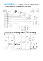
13.19.10
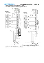
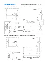
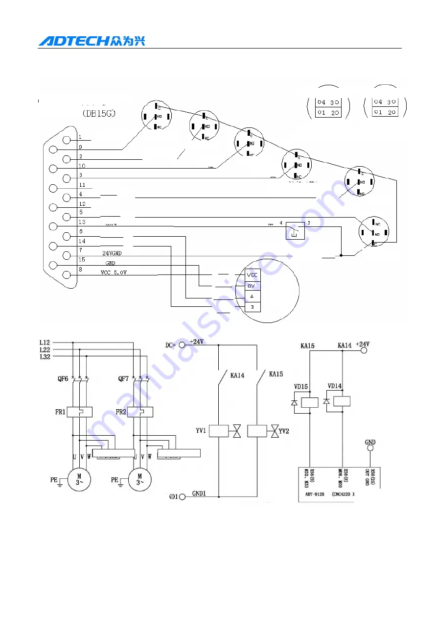
ADDITIONAL PANEL WIRING DIAGRAM
13.19.11
COOLING AND LUBRICATION WIRING DIAGRAM
Cooling electromagnetic valve/lubrication electromagnetic valve
CNC4220 additional panel
Interface
definition
Normally open
Normally open
Normally closed Normally closed
Power on (green) Power off (red)
Light blue
Standby 3
Standby 2
Standby 1
Pink
Orange
White
Cooling (yellow)
Start
Start (green)
Brown
Stop
Emergency stop Purple
Phase A
Phase B
Emergency stop button
Grey
Pause (red)
Red
Black
Yellow
Blue
H
andw
he
el
green
RC absorber
Cooling motor Lubrication motor
RC absorber
L
ubr
ic
at
ion
C
ool
ing
XS6
interface

