C N C 4 2 2 0 M a c hi ne Too l Op e ra t ion an d Te st
20
2.
Safe operation
2.1
Hardware overtravel protection
The overtravel protection is the necessary measure for the machine tool to prevent damage caused
when the X axis and Z axis exceed the travel. The hardware overtravel protection function is enabled
and controlled by system parameter 22 --- hard limit, which is enabled if the parameter is set to “1”.
The effective level of hardware limit is controlled by system parameter 23 --- effective level of hard
limit. Set the above two parameters according to the actual connection of the machine tool to realize
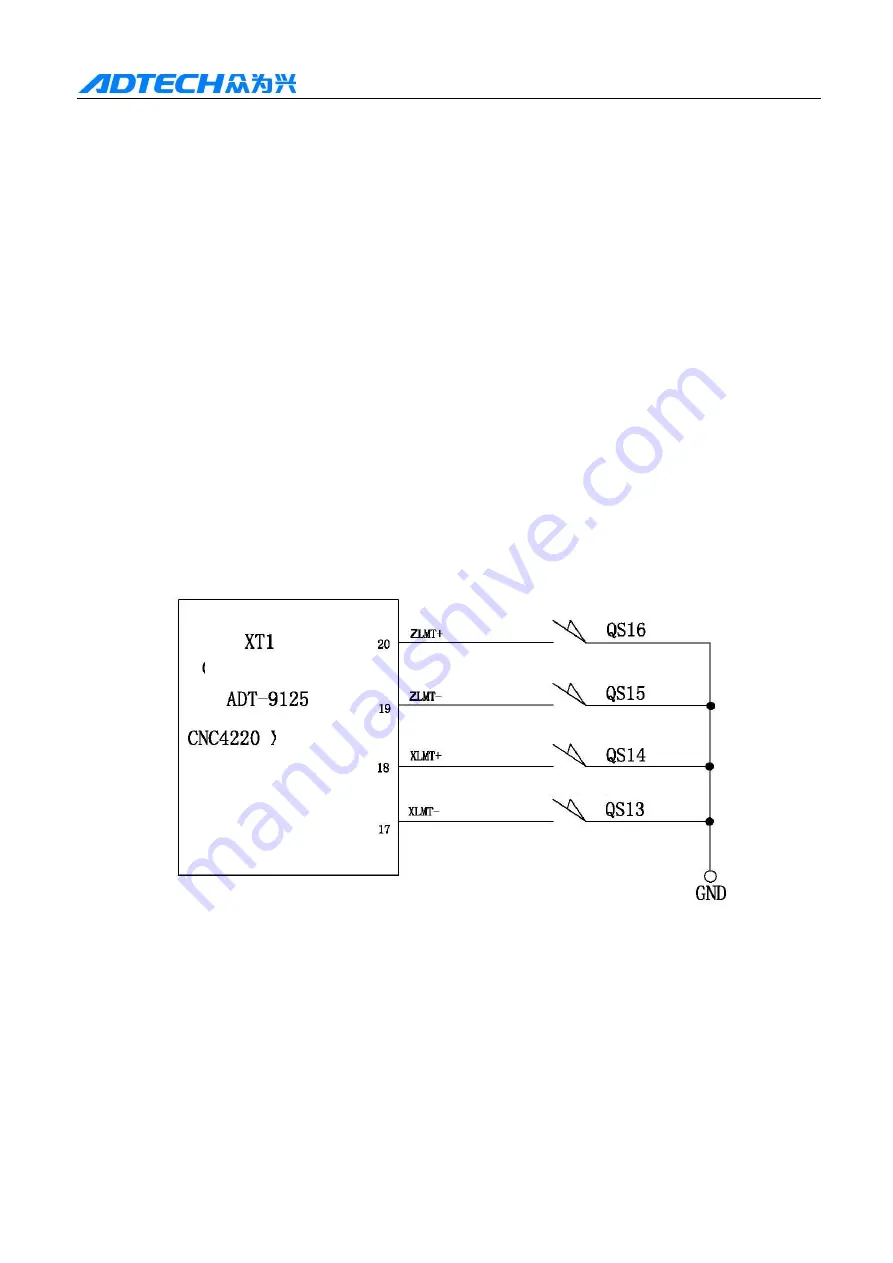
overtravel protection. Install travel limit switch in the position of maximum travel in positive and
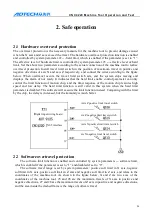
negative directions of axis X and axis Z respectively, and connect the wires according to the figure
below. When overtravel occurs, the travel limit switch acts, and the system stops moving and
displays the alarm of not ready. It indicates that the hard limit enable control parameter can only
control the limit function of motion chip, and the limit response of the motion chip features high
speed and low delay. The hard limit function is still valid in this system when the hard limit
parameter is disabled. The software will execute the limit function instead. Comparing with the limit
by the chip, the delay is increased, but the immunity is much better.
2.2
Software overtravel protection
The software limit function is enabled and controlled by system parameters --- software limit,
which is enabled if the parameter is set to “1” and disabled if set to “0”.
The software travel range is set by system parameters: positive soft limit in X axis, negative
soft limit in X axis, positive soft limit in Z axis and negative soft limit in Z axis, and refers to the
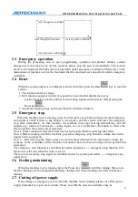
coordinates of the machine tool. As shown in the figure below, X and Z are two axes of the
coordinates of the machine tool, 25 and 26 are the maximum travels of X axis in positive and
negative directions, 27 and 28 are the maximum travels of Z axis in positive and negative directions,
and the area inside the dashed frame is the range of software travel.
Digital input wiring board
XS5 interface
Axis Z positive limit travel switch
xis Z negative limit travel switch
Axis X positive limit travel switch
xis X negative limit travel switch

