C N C 4 2 2 0 M a c hi ne Too l Op e ra t ion an d Te st
37
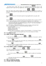
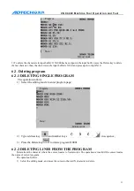
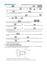
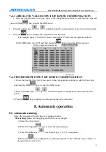
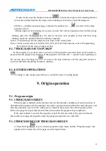
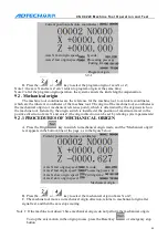
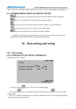
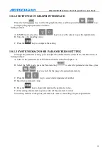
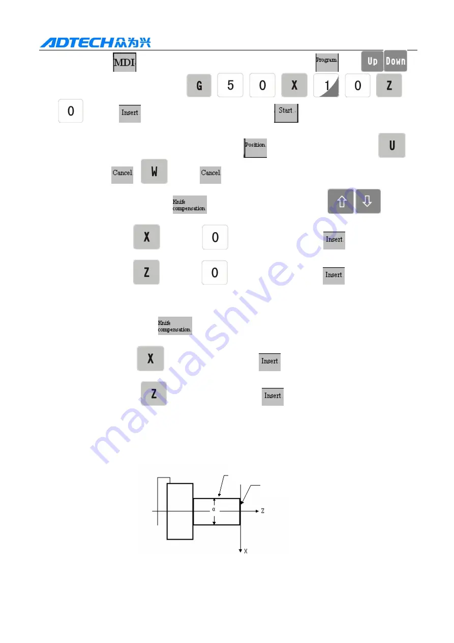
3) Press the MDI
key to enter the MDI mode, and press the Program key
(press
if
necessary) to enter the MDI page; type
,
,
,
,
,
,
,
and Insert
key in sequence, and then press the Start
key to set the actual values of axis
X and Z to the value to work piece coordinates
4) Clear the relative coordinates (U, W) (press the Position
→ turn page to relative position →
→
Cancel
→
→ Cancel
);
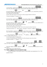
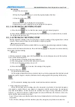
4) Press the Knife compensation key
to enter the bias interface, press the
/
key to
move cursor to select the corresponding bias number of the reference knife;
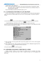
5) Press the address key
, number key
, and then press the Insert key
to set the bias of axis
X of reference knife to 0;
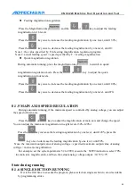
6) Press the address key
, number key
, and then press the Insert key
to set the bias of axis
Z of reference knife to 0;
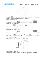
7) Move the knife to safe position, select another knife (set the bias number in the knife to 0) and move to the
alignment point, as Fig. B;
8) Press the knife compensation
key, and move the cursor to select the corresponding bias number of
the knife;
9) Press the address key
and then press the Insert key
to set the knife compensation value of
axis X to the corresponding bias number;
10) Press the address key
and then press the Insert key
to set the knife compensation value of
axis Z to the corresponding bias number;
11) Repeat step 7~10 to align other knives.
7.2.
Test cutting knife alignment
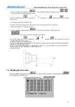
The test cutting knife alignment is valid if the system parameter 45 is 1. The operation follows
(create work piece coordinates with surfaces of the work piece):
1) Select knife 1 as the reference to make the knife cut along surface A;
2) Take out the knife along axis X when axis Z is still, and stop the rotation of main axis;
Surface B
Surface A

