C N C 4 2 2 0 M a c hi ne Too l Op e ra t ion an d Te st
46
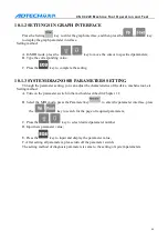
3-9-1
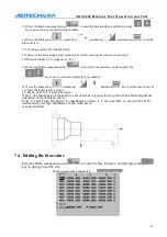
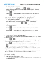
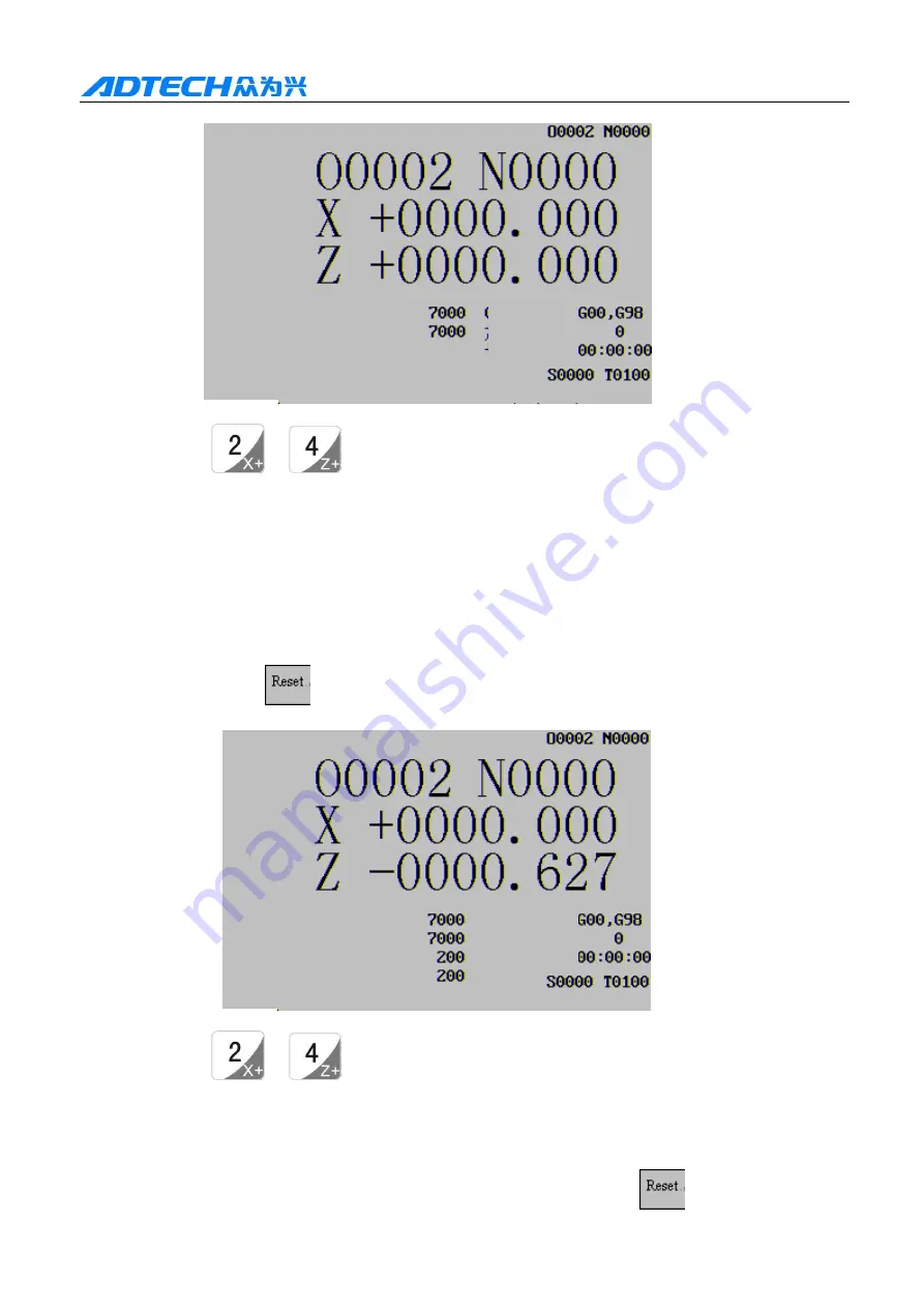
B. Press the
or
key to select the program origin of axis X or Z;
Note 1: the axis X and axis Z can’t return to program origin at the same time;
Note 2: after the program origin operation, the system cancels the knife length compensation.
9.2.
Mechanical origin
The machine tool coordinates are the reference for the machine tool to calculate coordinates,
which are the inherent coordinates of the machine tool. The origin of the machine tool coordinates is
the mechanical origin (or mechanical reference point), which is determined by the origin switch on
the machine tool. Generally, the origin switch is installed at the position of maximum travel in the
positive direction of axis X and axis Z (the origin direction can be set by relating system parameters)
9.2.1
PROCEDURES OF MECHANICAL ORIGIN
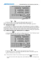
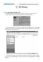
A. Press the Origin
key to switch to mechanical origin mode, and the “Mechanical origin”
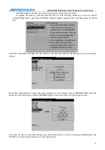
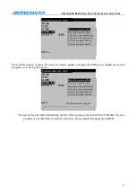
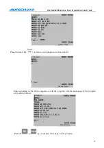
text appears in the bottom line of the page, as in the figure below:
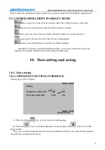
B. Press the
or
key to select the mechanical origin of axis X or Z;
C. The machine tool moves in mechanical origin direction, returns to mechanical origin after
signal test, and then the axis stops moving.
Note 1: If the machine tool doesn’t have mechanical origin, do not perform the mechanical origin.
To stop the axis motion in the origin process, press the Reset key
or emergency stop
button.
Current position (absolute coordinates)
Axis X fast origin speed: G code;
Axis Z fast origin speed: Processing pieces:
Cutting time:
Program origin
Current position (absolute coordinates)
Axis X fast origin speed: G code;
Axis Z fast origin speed: Processing pieces:
Axis X slow origin speed: Cutting time:
Axis Z slow origin speed:
Mechanical origin

