C N C 4 2 2 0 M a c hi ne Too l Op e ra t ion an d Te st
60
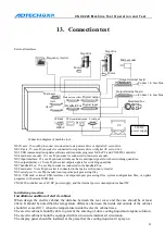
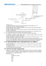
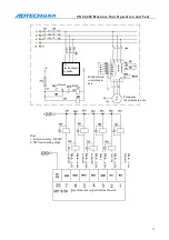
DC relay (24VDC)
Cable
between
the
system
and
strong
electricity cabinet
Cable
between
the
system and machine
tool
the cables in group B as far as possible from
group C
Cable
between
the
system and servo drive
Position
feedback
cable
Position encoder cable
Handwheel cable
C
Other
cables
for
shielding
Bind cables in group C separately from those in
group A, or shield the cables in group C; keep at
least 10cm between the cables in group B and
group C and use twisted pair cables
13.1.
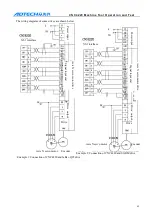
Motor drive connection test
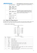
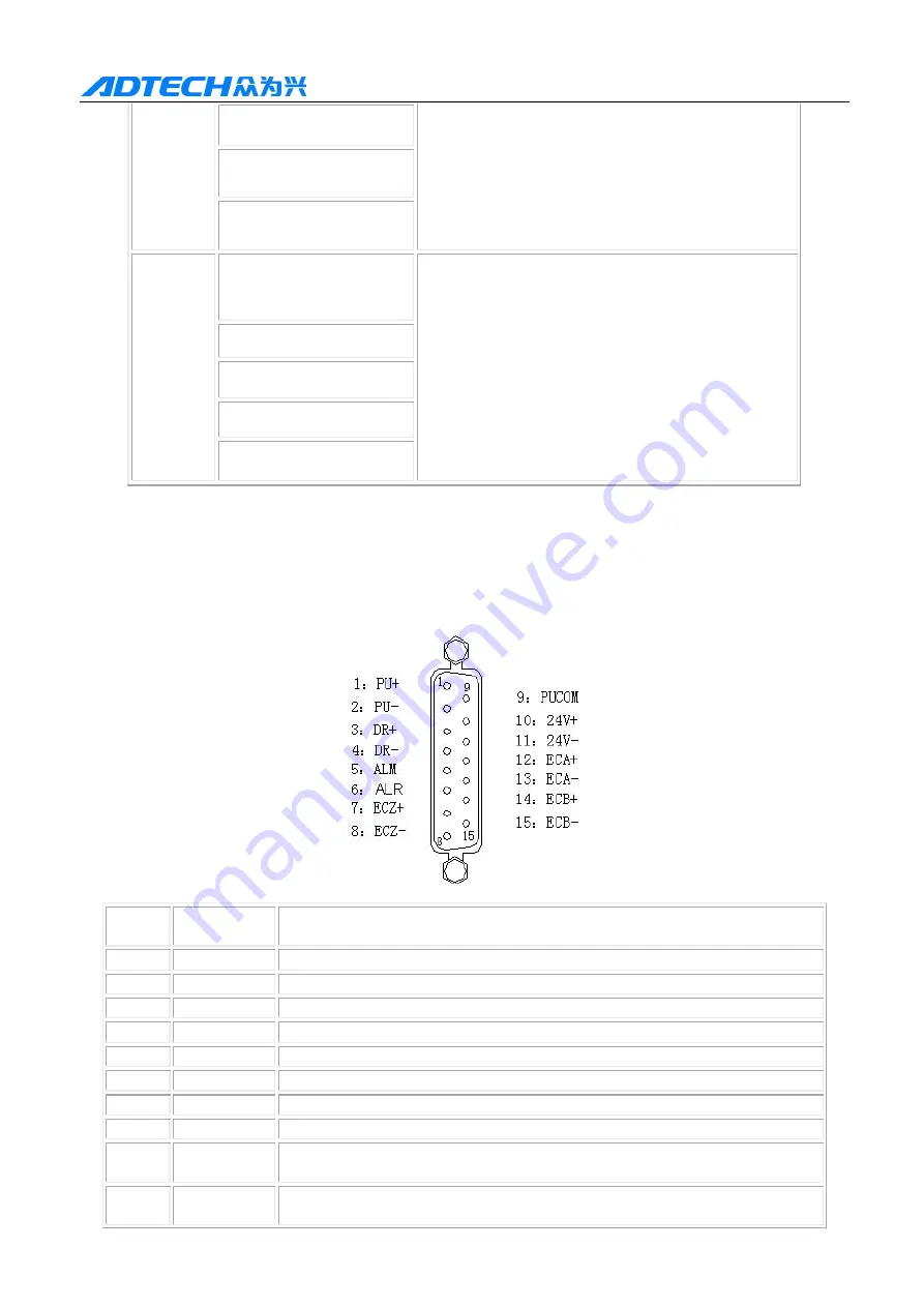
CNC4220 numerical control system integrates two step (or servo) motor drive interfaces (XS1 axis X
and XS2 axis Z); control mode: dir pulse (D+P); each interface pin has same function.
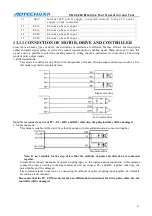
1. Function of drive interface pin
D efi n iti o n of dr i ve i nt er fa c es
X S1 a n d X S2 i nt er fa c e
Wire
No.
D efi n iti o n
sy mb o l
F u nct i o n
1
PU+
P uls e si g na l +
2
PU-
P uls e si g na l -
3
D R+
D ir ect i o n si g na l +
4
D R-
D ir ect i o n si g na l -
5
A LM
Ser v o a la r m si g na l a x is X : IN 3 4 , a x is Y: IN 3 5
6
A LR
Ala r m c lea r i n g a x is X : O U T2 4 , a x is Y: O U T2 5
7
E CZ+
E n c o der p ha se Z i n p ut +
8
E CZ-
E n c o der p ha se Z i n p ut -
9
PU CO M
Positive end of internal 5V power supply; can’t connect to external power
supply (drive for single end input)
10
2 4 V+
I nt er na l 2 4 V p o wer s u p pl y, c o n n ec te d dir e ctl y t o t h e 2 4 V p o w er
su p p l y o f t h e c o n tr o ll er

