C N C 4 2 2 0 M a c hi ne Too l Op e ra t ion an d Te st
69
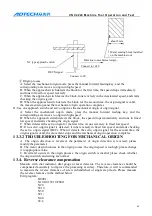
N50
M30.
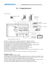
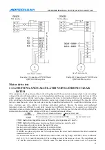
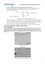
Set the error compensation of reverse clearance to 0 before measuring;
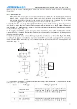
For single section program, find measurement reference A after positioning for two time,
record current data, run 1mm in same direction and then run 1mm to point B in reverse
direction to read current data.
Error compensation of reverse clearance = | data recorded by point A–data recorded by
point B |; if the clearance error isn’t 0, please modify the values of parameter 43 and 44
(unit: pulse); if the clearance is too big, increase the values of parameter 43 and 44, or
else decrease the values until the error compensation of reverse clearance is 0.
Note: Re-check the reverse clearance when the machine tool has been used for three months.
13.5.
Drive protection settings and checking
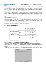
Drive alarm signal
The drive alarm function is always on and can’t be disabled, but the alarm effective level can be set in
the parameters. When the system is working and detects drive alarm signals, it compares with the
effective level set by the parameters and displays the corresponding alarm signals if it accords with the
parameter value. In auto mode, it stops running and sends alarm. Press the Diagnosis key to view the
alarm info and check the reason of the alarm. When the fault is eliminated, press the Reset key to clear
the alarm.
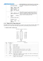
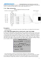
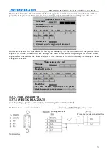
Axis X alarm info
Input point state
Axis X alarm signal AALM input valid
Reverse position
Position of reading data
Diagram of reverse clearance measurement method
Alarm info
Axis X positive direction overtravel
Alarm Auto mode

