C N C 4 2 2 0 M a c hi ne Too l Op e ra t ion an d Te st
70
Parameters: system parameter 30 and 31, axis X and axis Z alarm level. Default: “0”, low level is
effective; if the alarm is high output level, please change this parameter to “1”.
13.6.
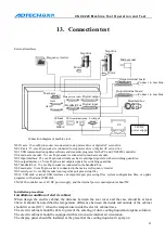
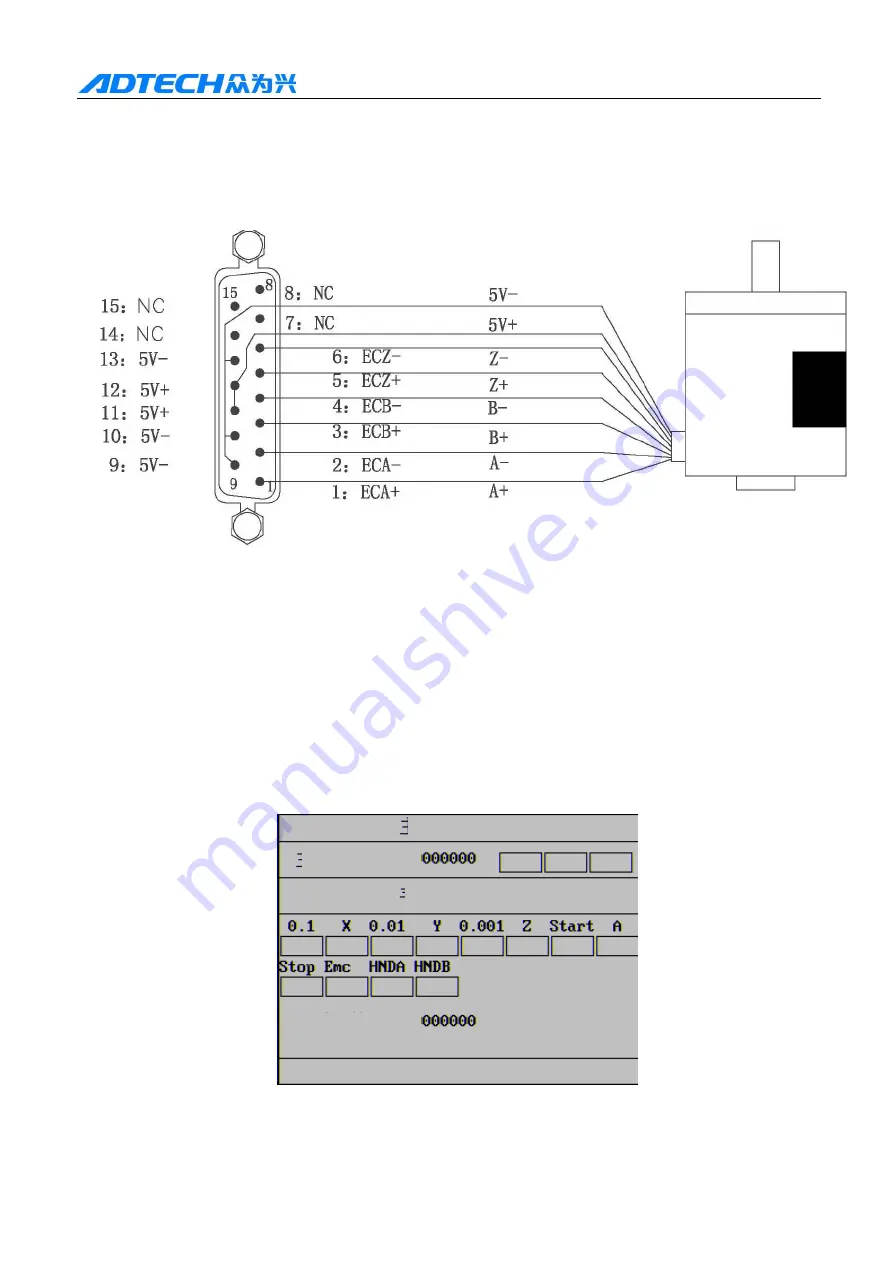
Main axis encoder
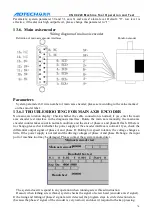
Wiring diagram of main axis encoder
Definition of main axis encoder interfaces Rotation encoder
Parameters
System parameter 60: wire number of main axis encoder; please set according to the value marked
on the encoder label.
13.6.1
TROUBLESHOOTING FOR MAIN AXIS ENCODER
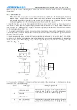
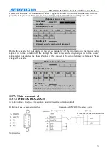
No main axis rotation display: Check whether the cable connection is normal; if yes, enter the main
axis encoder test interface in the diagnosis interface. Rotate the main axis manually, the main axis
encoder counter takes count in normal condition, and the stats of phase A and phase B flash. If there is
no change, please check whether the power supply of the encoder interface is normal. If yes, check the
differential output signal of phase A and phase B. During low speed rotation, the voltage changes a
little. If the power supply is normal and the driving voltages of phase A and phase B change, the input
port of machine tool may be damaged. Please contact the system manufacturer.
The system doesn’t respond to any operation when running screw thread instruction
Reason: when lathing screw thread, system checks the signal of screw head (encoder axis Z signal).
If the rising and falling of phase Z signal aren’t detected, the program stays in circle detection state
(because the phase Z signal of the encoder is very narrow) and doesn’t respond to the key-pressing.
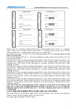
Main axis encoder test
Main axis encoder
Handheld box test
Handwheel

