C N C 4 2 2 0 M a c hi ne Too l Op e ra t ion an d Te st
75
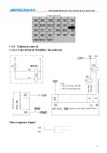
S10
1
0
1
0
S11
1
0
1
1
S12
1
1
0
0
S13
1
1
0
1
S14
1
1
1
0
S15
1
1
1
1
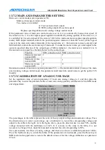
13.7.6
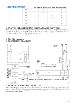
TROUBLESHOOTING FOR MAIN AXIS CONTROL
This part mainly involves the settings of frequency inverter, few involves the parameter setting of
machine tool control, and except the analog voltage, the state change of output signals of machine tool
controller can be checked in output point state interface.
13.8.
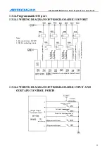
Chuck control
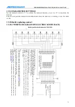
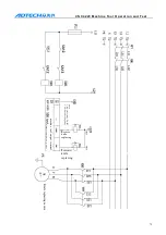
13.8.1
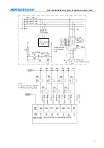
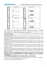
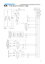
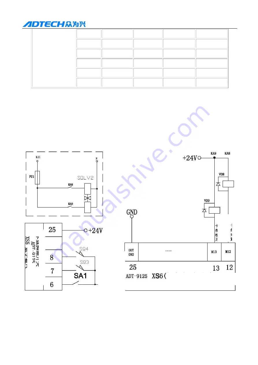
WIRING DIAGRAM
13.8.2
CHUCK PARAMETER SETTING
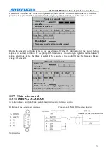
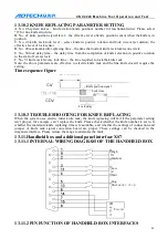
Check the clamping setting of chuck is “0” or “2” (do not check the clamp in position signal). The
shadow part is the chuck clamping time and controlled by the parameters. The output time sequence is
shown in the figure below.
C
huc
k c
la
m
p
ed
Note:
1. KA center relay, DC24V
2. VD Freewheeling diode
C
huc
k
re
le
as
ed
(machine tool output terminal board)
Clamping
signal
Release signal
C
huc
k f
o
ot
s
w
itc
h
D
igi
ta
l i
nput

