XT20100820 HC8200 Flame Cutting Machine User’s Manual
3-23
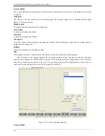
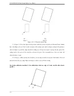
Figure 1 Figure 2
Figure 3.2.3.3.2 Principle of plate align
1
)
In Figure 1 of the above figure, the large frame (solid line) is the steel plate, and the small frame (dashed
line) is the Shape to be cut. Point A is the start point of the cutting torch, and if cutting according to the position as
shown in Figure 1, part of the shape outside the cutting area will not be cut, and if moving the start point of the
cutting torch to the center of the steel plate as shown in Figure 2, the unreasonable use of the steel plate will
obviously cause a waste.
2
)
In this case, without moving the steel plate, you can simply calculate the angle of inclination of the steel
plate and incline the processing Shape accordingly to achieve a more efficient cutting.
Steel plate calibration method 1: the calibration reference edge is X axis, and the direction is
positive.
Summary of Contents for ADT-HC8200
Page 5: ......
Page 11: ......
Page 22: ...Chapter 2 2 12 Figure 2 4 1 1 2 Side view of AIO controller...
Page 25: ......
Page 93: ......


