background image

Chapter 3


 Function and Operation 


3-38

 
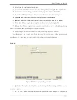
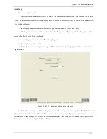
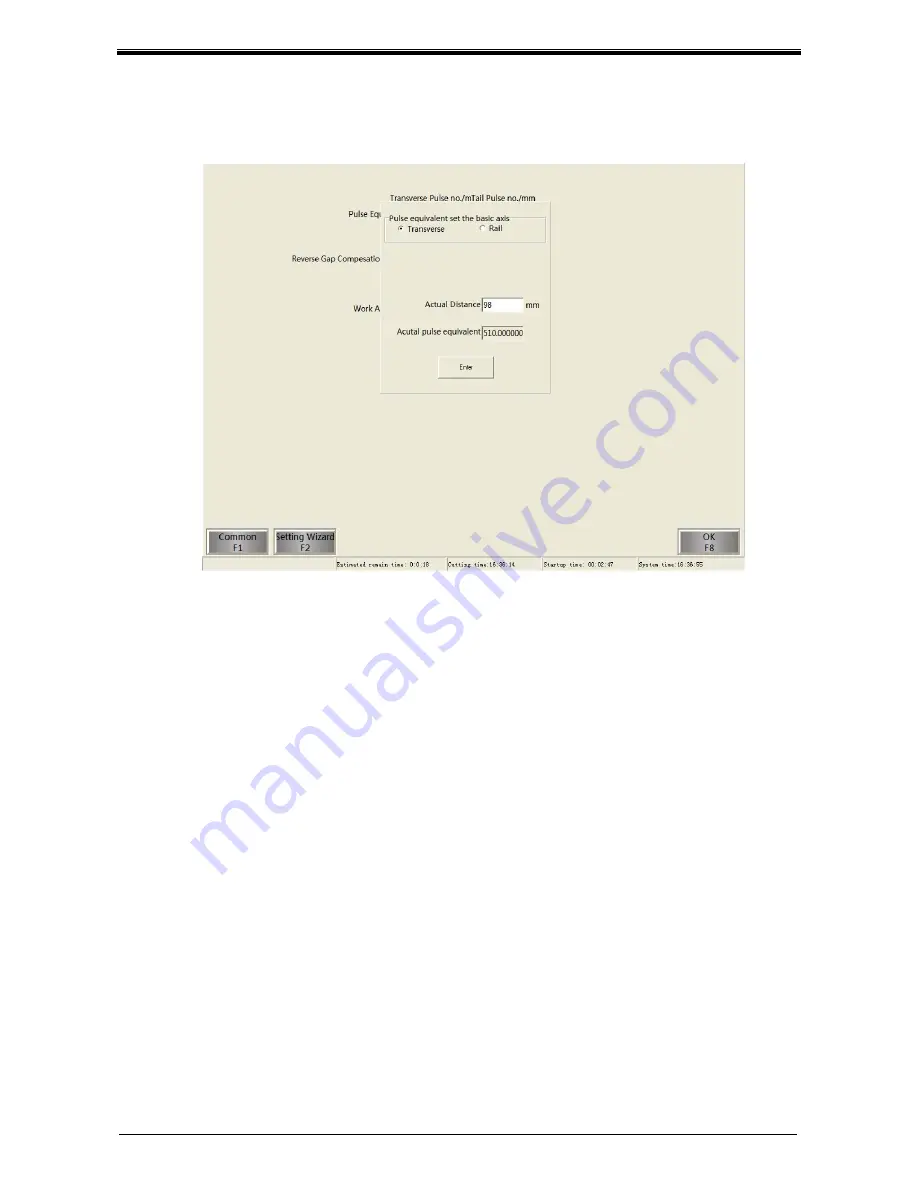
3) Use the measuring tool to measure the actual moving distance at the direction of the selected axis, and 

enter this value into the Actual distance as shown in Figure 3.2.4.3.5, then press Enter, the actual pulse offset will 
display in Actual pulse offset, as shown in Figure 3.2.4.3.6. 


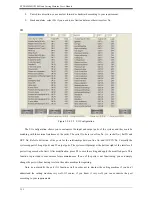
Figure 3.2.4.3.6 Accuracy setting completed 


4) Press Enter, system will save the pulse offset and the accuracy guide is completed. Users may repeat the 

above steps to set pulse offset for different axis or the same axis. 

Note: normally, slight difference may occur in the pulse offsets of the X axis and Y axis in the same 

equipment, so you need to set them respectively in the adjustment (it is recommended to adjust them to be the 

same with each other). 


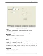
System 

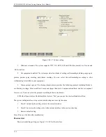
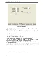
Other settings for the control of the system are shown in the figure below: 

Summary of Contents for ADT-HC8200

Page 1: ...CNC System User s Manual Adtech Shenzhen Technology Co Ltd Add F 5 Bldg 27 29 Tianxia IC Industrial Park Yiyuan Rd Nanshan District Shenzhen Postal code 518052 Tel 0755 26099116 Fax 0755 26722718 emai...

Page 2: ...ohibited This manual doesn t contain any assurance stance or implication in any form Adtech and the employees are not responsible for any direct or indirect data disclosure profits loss or cause termi...

Page 3: ...Contents Basic Manual Info Item No First uploaded on Version No Pages Compiled by Typeset by XT20100820 2012 6 01 A0501 96 Pan Jian Revision Date Version Page Result Confirmed by...

Page 4: ...before repairing or replacing the components Check the failure if short circuit or overload occurs and restart after eliminating all failures Do not connect cut off the power supply frequently wait fo...

Page 5: ......

Page 6: ...Descriptions to the keys under main interface 3 5 3 2 1 F1 Shape 3 5 3 2 2 F2 Files 3 13 3 2 3 F3 Part Options 3 17 3 2 4 F4 Setups 3 26 3 2 5 F5 View sheet 3 46 3 2 6 F6 Cut mode 3 48 3 2 7 F7 Start...

Page 7: ...hapes 5 2 5 1 Standard circle 5 2 5 2 Square 5 3 5 3 Triangle 5 4 5 4 Quincunx 5 5 5 5 Four circle shape 5 5 6 Chapter VI Command List 6 2 6 1 G command inquiry 6 2 6 2 M command inquiry 6 2 6 3 EIS c...

Page 8: ...eys from F1 to F8 Code display display G code of the image to be cut IO Monitor display output statues under current cutting mode Speed meter display current cutting speed Parameter setting currently...

Page 9: ...e RS232 communication interface and two Ethernet interfaces The main function includes 1 WINDOWS XP operation system multi language human computer interface 2 Slotting Kerf compensation 3 Rotating and...

Page 10: ...transformation between CAD and DXF files 27 Support Shapes library 28 Support touch screen and standard PS 2 and USB keyboard 29 Support USB removable storage devices 30 Built in diagnosis function h...

Page 11: ......

Page 12: ...C communication The two interfaces are 37 pins and 64 pins respectively Input power supply power supply interface for interface board the power input is 24V Axis input output interface interface for p...

Page 13: ...XT20100820 HC8200 Flame Cutting Machine User s Manual 2 3 2 2 Overall connection Figure 2 2 1 Overall connection...

Page 14: ...f X axis 3 XDR Positive direction signal of X axis 4 XDR Negative direction signal of X axis 5 INT21 Location arriving signal of X axis 6 OUT27 X servo alarm clear 7 XECZ 8 XECZ 9 VCC5V 5V power outpu...

Page 15: ...Positive direction signal of Y1 axis 4 XDR Negative direction signal of Y1 axis 5 INT23 Position arriving signal of Y1 axis 6 OUT27 Y1 servo alarm clear 7 XECZ 8 XECZ 9 VCC5V 5V power output 10 VCC_2...

Page 16: ...nal of Y2 axis 4 XDR Negative direction signal of Y2 axis 5 INT25 Position arriving signal of Y2 axis 6 OUT27 Y2 servo alarm clear 7 XECZ 8 XECZ 9 VCC5V 5V power output 10 VCC_24V 24V power output 11...

Page 17: ...3 XDR Positive direction signal of Z axis 4 XDR Negative direction signal of Z axis 5 INT27 Position arriving signal of Z axis 6 OUT27 Z servo alarm clear 7 XECZ 8 XECZ 9 VCC5V 5V power output 10 VCC_...

Page 18: ...r supply alarm 3 IN1 Negative limit of X axis 4 IN13 Plasma arc striking succeeded 5 IN2 Positive limit of Y axis 6 IN14 Plasma anti collision 7 IN3 Negative limit of Y axis 8 IN15 Initial orientation...

Page 19: ...g 2 3 3 General output interface Figure 2 3 1 General output interface Line No Name Function 1 OUT0 Ignition 2 OUT15 Cutting torch 3 selection 3 OUT1 Fuel gas 4 OUT16 Cutting torch 4 selection 5 OUT2...

Page 20: ...g 21 OUT10 Plasma local drop 22 OUT25 Standby 1 23 OUT11 Plasma all rise 24 VCC_24V 24V power output 25 OUT12 Plasma all drop 26 VCC_24V 24V power output 27 OUT13 Cutting torch 1 selection 28 OGND 24V...

Page 21: ...XT20100820 HC8200 Flame Cutting Machine User s Manual 2 11 2 4 Installation dimension charts 2 4 1 Controller dimensions 2 4 1 1 AIO Figure 2 4 1 1 1 Front view of AIO controller...

Page 22: ...Chapter 2 2 12 Figure 2 4 1 1 2 Side view of AIO controller...

Page 23: ...XT20100820 HC8200 Flame Cutting Machine User s Manual 2 13 2 4 1 2 Non AIO Figure 2 4 1 2 1 Host dimension chart of non AIO Figure 2 4 1 2 2 Monitor dimension chart of non AIO...

Page 24: ...Chapter 2 2 14 Figure 2 4 1 2 3 Monitor dimension chart of Keyboard 2 4 2 Interface board dimensions Figure 2 4 2 1 Interface board dimension chart...

Page 25: ......

Page 26: ...pe The system requires a Dongle to run so make sure the Dongle works well before powering on In addition when using the system it is required to connect to an IO interface board so check whether the I...

Page 27: ...1 2 Main interface The system provides rich functions and is easy to operate Users may press a corresponding key under the main interface to operate the processing components and codes Allocation of t...

Page 28: ...the Files interface you can read files from controller or U disk create copy or delete a file or preview the shape to be operated it also provides the functions such as U disk ejection and resumes pa...

Page 29: ...orners of the components Zero Position To set the current position as the reference origin at this time you can see the position of the cursor in the preview window This function also allows you to re...

Page 30: ...quently used Shapes and one testing shape as shown in Figure 3 2 1 1 1 below Figure 3 2 1 1 1 Shape library Under this interface you can press or to select a shape and then press F8 to confirm and ent...

Page 31: ...m enters Auto interface automatically under which users may use this processing file directly If ESC is pressed the processing file in the system will remain unchanged and the setting is not applied U...

Page 32: ...ab to preview automatically if the parameters exceed the limit the system will prompt Take the parameter setting interface of the convex polygon with a hole as an example if the radius of the circle i...

Page 33: ...ns interface under which you can perform the operations such as rotate array rotate zoom in and mirror After modifying the code press F2 to view the shape If you want to save the modified code simply...

Page 34: ...sting and auto nesting and allows the user to put the different shapes together for cutting which greatly improves the utilization rate of the materials Structure and functions of shape nesting interf...

Page 35: ...all nesting parts and ingle part display when displaying a single part all nesting parts are displayed in the display area Setups Set relevant parameters of the Shape nesting OK Stop nesting and retu...

Page 36: ...required Click Slotting compensation on the tool bar then select the closed curve requiring compensation the system will prompt a message to ask if you need left compensation or right compensation and...

Page 37: ...ions To rotate array rotate zoom in or mirror the Shape Shape preview To preview the Shape whose code is modified Text Save To save the modified code OK To complete editing and return to main interfac...

Page 38: ...3 Function and Operation 3 14 Figure 3 2 2 1 File management interface The Structure and functions of files interface are as shown in the figure below Figure 3 2 2 2 Structure and functions of files i...

Page 39: ...The Code editing interface provides the functions including Edit code Part options Shape preview and View sheet See Code editing interface for details New File Create a new file Enter U Disk To copy a...

Page 40: ...over the saved part or in case of power failure during the cutting if a UPS is provided the system will save the part automatically after receiving power alarm and when power supply resumes you can pr...

Page 41: ...ed from the U disk can only be G or EIS or DXF file The system doesn t support other types of files 3 2 3 F3 Part Options Under this interface you can manage the processing parts Under the main interf...

Page 42: ...The offset between the parts Rotate angle To rotate the processing Shape anticlockwise at a certain angle Zoom coefficient To zoom in or zoom out the Shape according to actual size zoom in when the va...

Page 43: ...after modification will be displayed immediately as shown in the figure below Figure 3 2 3 3 Parts Shape There are five function keys under Parts manager interface The details are as follow 3 2 3 1 F...

Page 44: ...Chapter 3 Function and Operation 3 20 Figure 3 2 3 1 1 Kerf display interface Press this key again to cancel display 3 2 3 2 F2 Repeat The controller provides two repeat methods straight and stagger...

Page 45: ...XT20100820 HC8200 Flame Cutting Machine User s Manual 3 21 Straight Repeat Figure 3 2 3 2 1 Straight Stagger Repeat Figure 3 2 3 2 2 Stagger resorting Parameters under resorting...

Page 46: ...components or component complexes Waste edge value To specify the waste width between components the waste edge values of X axis and Y axis are the same 3 2 3 3 Sheet Align This function allows you to...

Page 47: ...own in Figure 1 part of the shape outside the cutting area will not be cut and if moving the start point of the cutting torch to the center of the steel plate as shown in Figure 2 the unreasonable use...

Page 48: ...l be saved for next use 2 In such case the Shape will be rotated at an angle accordingly The positions of the Shape to be processed and the steel plate are as follow Figure 3 2 3 3 4 Result of align w...

Page 49: ...method 1 only the reference axis is different Sometimes the steel plate on X axis is too short in this case we can select to calibrate based on Y axis Before align select the base axis and direction...

Page 50: ...turn to main interface and use the current Shape as the cutting program 3 2 4 F4 Setups The system setting main interface where you can set main parameters as shown in the figure below Figure 3 2 4 1...

Page 51: ...XT20100820 HC8200 Flame Cutting Machine User s Manual 3 27 Figure 3 2 4 2 Structure and functions of system setups interface...

Page 52: ...0 Kerf width Width of kerf with the value greater than 0 Cutt mode The system provides the following cutting modes preview oxygen gas plasma spraying and plasma mark These options can be added or rem...

Page 53: ...g signal remains valid before high preheating This time can be prolonged cancelled or modified 4 High preheat time The time of the high preheating signal before every perforation This time can be prol...

Page 54: ...ration time setting 15 Lock gas Whether to open the gas during preheat 16 Keep preheat in cut process Whether or not to enable preheating while cutting 17 Multi level perforation Whether or not to ado...

Page 55: ...time The time for delay in closing after completing of cutting When cutting completes delay in stop of cutting gas will maintain the cutting arc and enlarge width of cutting path thus this parameter...

Page 56: ...ter is applied whether or not the local rising is valid 17 Initial position When no height adjuster is applied select whether or not to use this initial positioning function If it is needed then a pos...

Page 57: ...Plasma marking parameters 1 Mark arc strike time The time delay for each marking arc striking 2 Mar arc OFF time The time delay for arc closing while arc blowout 3 Mark up time The time for marking r...

Page 58: ...Transverse axis or Rail axis according to your requirements 2 Up arrow direction you can define the axis according to your requirements mainly depending on placement of the machine 3 Right arrow direc...

Page 59: ...orts for the relationships between line No and OUT IN No Currently the system supports 28 input ports and 29 output ports The system will prompt at the bottom right of the interface if port setting ex...

Page 60: ...eds the allowed size of the workbench Accuracy setting guide set the pulse offset through a guide Example of pulse equivalent setting 1 Under the Accuracy setting interface press F2 to enter Accuracy...

Page 61: ...achine User s Manual 3 37 Figure 3 2 4 3 4 Accuracy setting test process When the selected axis is tested and moved the following interface will appear as shown in the figure 3 2 4 3 5 Figure 3 2 4 3...

Page 62: ...re 3 2 4 3 6 Accuracy setting completed 4 Press Enter system will save the pulse offset and the accuracy guide is completed Users may repeat the above steps to set pulse offset for different axis or t...

Page 63: ...vides the following prompts including Ready to cut Slotting too large Value modified Component larger than plate Component modified and Save component for recovery Users can select the prompts accordi...

Page 64: ...d setting Enter the password and press Enter Enter the new password and press Enter to confirm After setting press F8 to save the data 3 2 4 4 F4 Speeds Under system setting interface press F4 speed p...

Page 65: ...me Speed when home the machine moves at high home speed at first and decelerates and stops when hitting the switch and then moves back at low home speed until signal disappears 8 Creep speed the machi...

Page 66: ...eration 3 42 Figure 3 2 4 5 1 Exit interface Restart Restart the PC Shut down Shut down the PC Exit System Exit cutting system 3 2 4 6 3 2 4 6 F6 Watch Under System setting interface press F6 to enter...

Page 67: ...Machine User s Manual 3 43 Figure 3 2 4 6 1 System diagnosis interface Information It displays the hardware information software information controller information etc of the controller I O test Figu...

Page 68: ...to I O setting above Keyboard Test Press F3 to enter Keyboard testing interface as shown in the figure below Figure 3 2 4 6 3 Keyboard test Once you press a key it will be displayed in this interface...

Page 69: ...ey in the keyboard at the corresponding position and the pressed key will be displayed on the screen If no response on the screen even after a key is pressed for many times or the position is not corr...

Page 70: ...will start Min pierces Generally speaking perforation may reduce the useful life of the wearing parts This parameter allows the user to input the time required for each perforation and calculate this...

Page 71: ...XT20100820 HC8200 Flame Cutting Machine User s Manual 3 47 Figure 3 2 5 1 Plate interface Figure 3 2 5 2 Parts interface...

Page 72: ...supports preview oxygen gas plasma powder spray marking and plasma marking As shown in figure 3 2 6 1 the cutting mode is displayed in the red circle marked in the interface Figure 3 2 6 1 Oxygen gas...

Page 73: ...Figure 3 2 6 2 Plasma cut mode 3 2 7 F7 Starting point of cutting Press F7 under the main interface to switch the start point of the Shape to be cut as shown in the figure Figure 3 2 7 1 Switch start...

Page 74: ...according to a certain law based your setting and the system will check whether your setting is reasonable If the speed parameter you set is not able to satisfy the requirements of the system then th...

Page 75: ...unction keys Return To Start To press this key the cutting torch will return to starting point directly namely the origin of the relative coordinates Backup Press and hold F2 the cutting torch will co...

Page 76: ...he perforation point You can select in three different ways S N Forward and Backward After entering the data press Enter and the cutting torch will move to the corresponding ignition point then press...

Page 77: ...interface press the or key to zoom in or zoom out the Shape Press once the Shape zooms in by 2 times and press once the Shape zooms out by 1 2 Press Shift and or at the same time you can translate th...

Page 78: ...perforating and cutting at the position of the trail Directly cut and return means to perforate at the current position and then start cutting Idle return and stop means the torch stops after idle re...

Page 79: ...ress keys to stop moving or to start moving You can modify manual moving speed while it is stopped and press Enter to apply the modification When the manual moving is stopped press ESC to return to ma...

Page 80: ...F8 to return to previous interface namely the main interface 3 4 System function keys The system function keys are valid in the main interface manual interface pause interface and cutting interface on...

Page 81: ...ng and high preheating will change from open to close or from close to open THC Press THC under the main interface manual interface pause interface or cutting interface the I O port of the THC will ch...

Page 82: ...oordinate value under G91 by default and absolute coordinate value under G90 Y Y axis coordinate value relative coordinate value under G91 by default and absolute coordinate value under G90 I The diff...

Page 83: ...point D is Y 50 5 When point D returns to point B the coordinate is X 50 4 2 2 Absolute coordinates In the coordinate system if the position of a coordinate point is calculated from the coordinate of...

Page 84: ...achine tool origin positioning 4 3 2 G00 Idle replacement motion This command realizes moving to the specified position in a rapid way While displacement the system moves at a straight line from the s...

Page 85: ...on Expected cutting torch position Figure 4 3 3 1 Straight line cutting 4 3 4 G02 G03 Arc cutting This command is used to cut an entire circle or an arc The circle can be divided into G02 clockwise an...

Page 86: ...ands G91 G90 Relative absolute coordinates G41 G42 Left right slotting compensation G40 Cancel slotting compensation 4 3 6 M commands The system is customized with a supplementary command M44 This com...

Page 87: ...splacement of the X coordinate of the end point related to the starting point of the current arc segment unit mm Y Displacement of the Y coordinate of the end point related to the starting point of th...

Page 88: ...arting point of cutting Remark as absolute coordinates are not usually used it is not introduced in this Manual All of the following examples adopt relative coordinates 5 1 Standard circle Figure 5 1...

Page 89: ...uare Relative coordinates programming and Shape codes 0000 G92 X0 Y0 0001 G00 X50 Y50 Idle displacement 0002 G01 Y50 The first edge 0003 G01 X50 The second edge 0004 G01 Y 50 The third edge 0005 G01 X...

Page 90: ...amples for Editing and Processing Graphics 5 4 5 3 Triangle Figure 5 3 1 Triangle Relative coordinates programming 0000 G92 X0Y0 0001 G00X50 Y50 0002 G01X50Y50 0003 G01Y 50 0004 G01X 50 0005 G00X 50Y...

Page 91: ...5 4 Quincunx Figure 5 4 1 Quincunx Relative coordinates programming 0000 G92 X0Y0 0001 G00 X75Y75 0002 G02Y100I0 J50 0003 G02X100I50J0 0004 G02Y 100I0 J 50 0005 G02X 100I 50 J0 0006 G00X 75Y 75 0007...

Page 92: ...X 200 0006 G00 Y400 0007 G01 Y50 0008 G02 X50 Y50 I50 J0 0009 G01 X100 0010 G02 X50Y 50 I0 J 50 0011 G01 Y 100 0012 G02 X 50 Y 50 I 50 J0 0013 G01 X 100 0014 G02 X 50 Y50 I0 J50 0015 G01 Y50 0016 G00...

Page 93: ......

Page 94: ...ription 1 G00 Rapid point motion idle running 2 G01 Straight line processing 3 G02 Clockwise circle processing 4 G03 Anticlockwise circle processing 5 G92 Processing reference point setting 6 2 M comm...

Page 95: ...gment starts 2 4 Explanation segment ends 3 63 Program completes 4 29 30 Kerf compensation 5 38 Cancel kerf compensation 6 Is Js Straight line displacement 7 X Y I J Clockwise arc displacement 8 X Y I...

Page 96: ...eleration and corner speed in System setting Speed parameters Cutting quality 6 There is diagonal dithering while cutting circle Adjust the Accuracy setting in System setting Encryption setting and se...

Page 97: ...Feedback by Date 2011 12 2 Current version Page V0 1 0 108 Description Update descriptions to the adjustment of organizational structure and modification of interface of HC8200 software Confirmed by...

Reviews: