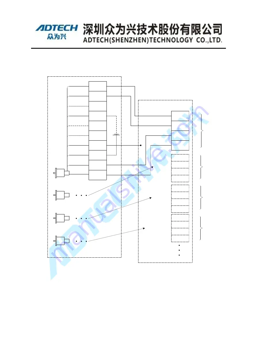
Wiring of Electrical Power
Motor2
(
J2
)
Motor1
(
J1
)
Peach
Blue
Brown
PS+
PS-
BAT-
Vacant
Vacant
FG
E5V
BAT+
1
Battery
2
3
4
5
6
7
8
9
5V
GND
PS1-
PS1+
White/Black
White/Red
Gray/Black
Gary/Red
Motor 1
Motor 2
Motor3
(
J3
)
Motor4
(
J4
)
Orange/Red
Orange/Black
Pink/Red
Pink/Black
5V
GND
PS2+
PS2-
5V
GND
PS4+
PS4-
Orange/Black/Black
Orange/Red/Red
White/Black/Black
White/Red/Red
5V
GND
PS3+
PS3-
Gray/Black/Black
Gray/Red/Red
Yellow/Black
Yellow/Red
Motor 3
Motor 4
Definition of Encoder
Definition of 26-pins Cable
Others are not used
Purple
Vacant
Red
E0V
10
Black
Shield
Shield Cable
17-bits Absolute motor of SANYO
Figure 4-9 Sanyo Electric power line side wiring
Notes:
Motor-side encoder cable, power cable terminal color definitions for reference only,
actual colors and line number with manufacturers to provide prevail; power lines cannot be
connected to the end of the shielded cable with the encoder shielded wire to wire ends
together; the motor brake via 16pin cable Relay terminal control line can also be controlled
through the relay output terminal board.


