Motor3(J3)
Blue
BK
BK
Yellow
Brake Definition for SANKYO-17Bits
Absolute
Motor2(J2)
Blue
BK
BK
Yellow
Blue
BK
BK
Yellow
Motor1(J1)
Motor4(J4)
Blue
BK
BK
Yellow
R
B
Y/G
W
W
R
B
Y/G
W
W
R
B
Y/G
W
W
R
B
Y/G
W
W
Y/G
Y/G
Y/G
Y/G
PinkRed
PinkBlack
WhiteRedRed
WhiteBlackBlack
OrangeRedRed
Internal
24V
Relay4
Relay3
Relay2
Relay1
Brake Adapter Plate
IO Cables of 16 Pins
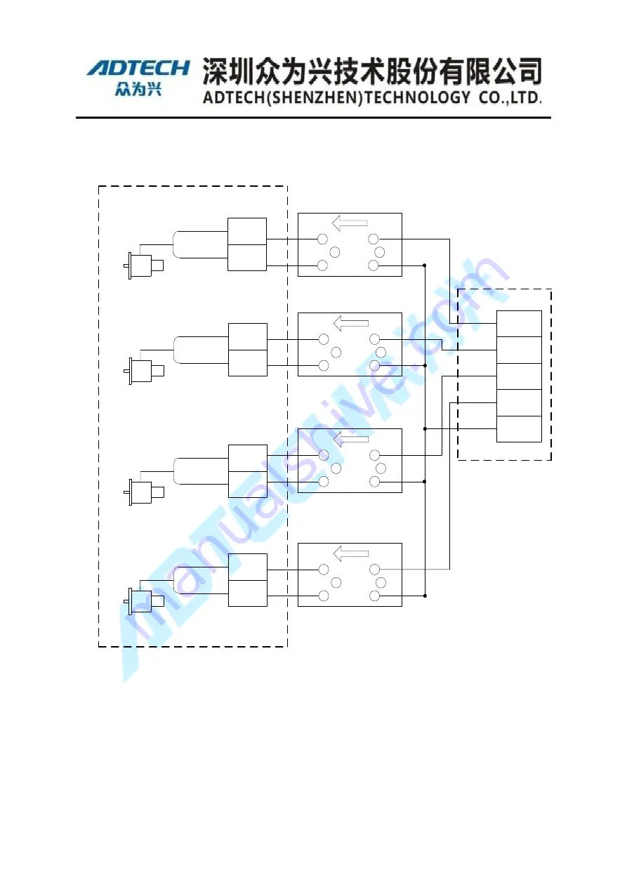
Figure 4-13 Brake Wiring of SANKYO Motor
For practical application, you must finish brake wiring based on the robot used firstly.
Then configure brake port, please refer to
【
Teaching Pendent Operation
】
.
4.4 Signals’ Definition for <48Pin> Motor Terminal
Table 4-4-1 48Pin Heavy load connector instruction


