36
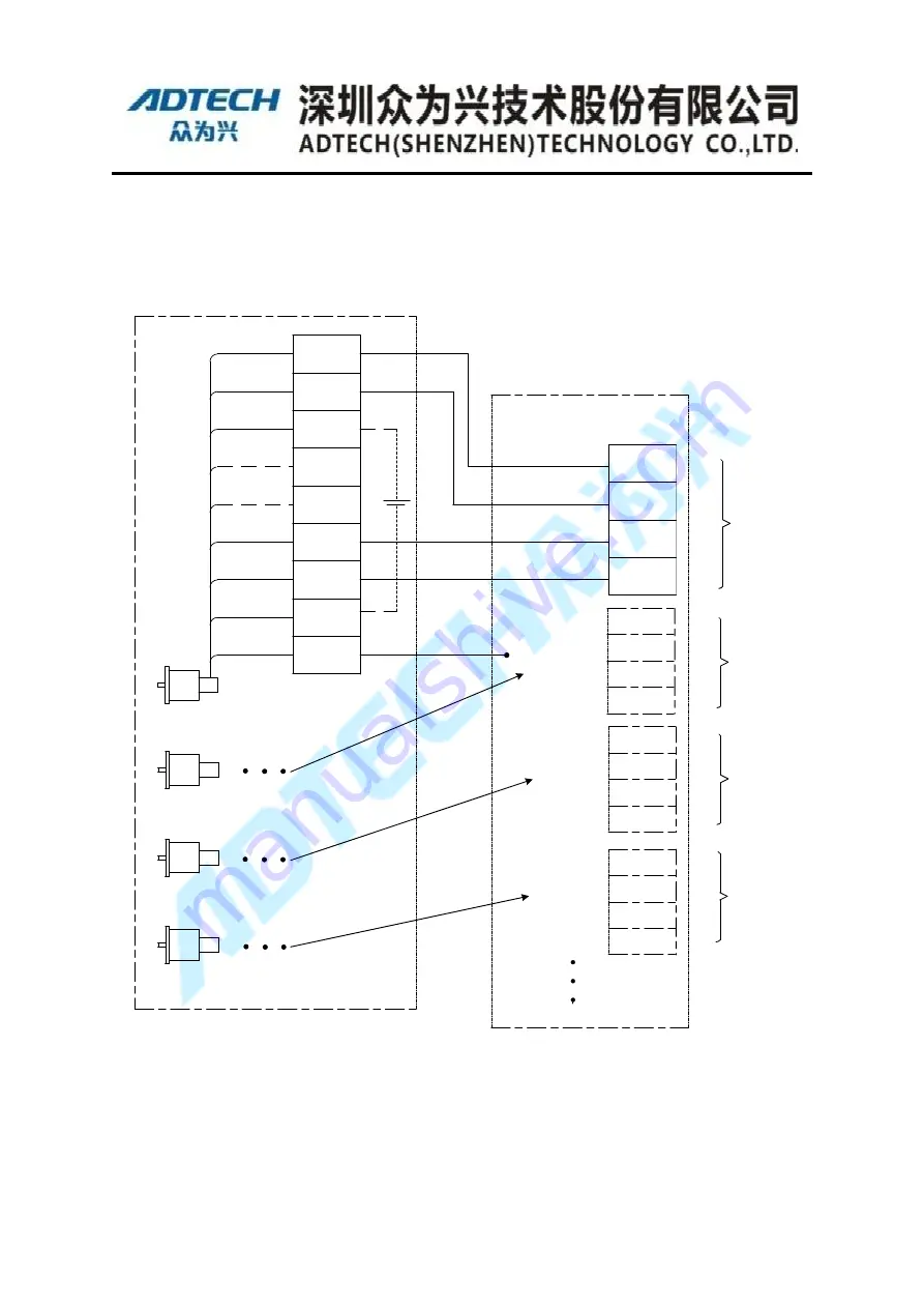
4.3.2 Tamagawa Motor Wiring Instance
Wiring of 17bits Absolute Encoder
Motor2
(
J2
)
Motor1
(
J1
)
Purple/White
Blue/White
Blue
PS+
PS-
BAT+
Vacant
Vacant
E5V
E0V
FG
BAT-
Purple
Green/White
1
Battery
2
3
4
5
6
7
8
9
5V
GND
PS1-
PS1+
White/Black
White/Red
Gray/Black
Gray/Red
Motor 1
Motor 2
Motor3
(
J3
)
Motor4
(
J4
)
Orange/Red
Orang/Black
Pink/Red
Pink/Black
5V
GND
PS2+
PS2-
5V
GND
PS4+
PS4-
Orange/Black/Black
Orange/Red/Red
White/Black/Black
White/Red/Red
5V
GND
PS3+
PS3-
Gray/Black/Black
Gray/Red/red
Yellow/Black
Yellow/Red
Motor 3
Motor 4
Definition of encoder
Definition of 26-pins Cable
Others are not used
Green
Shield
Shield Cable
17-bits Absolute Motor of TAMAGAWA
Figure 4-5 Tamagawa motor encoder line wiring


