background image

ADT-

TH08HA-Spring Machine System

18

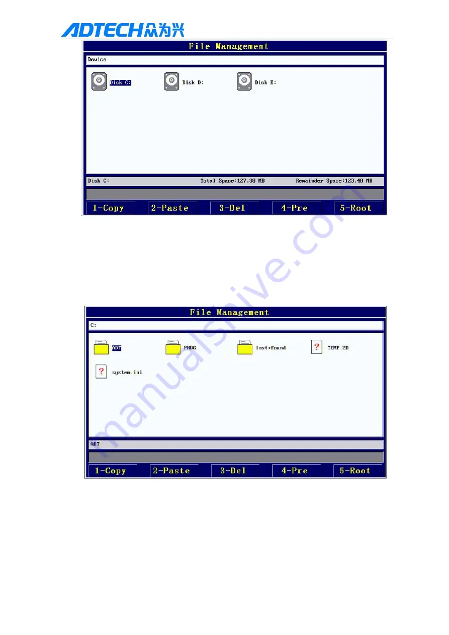
Figure 3.2

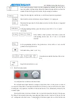
At this point you can press up and down arrow keys to select the disk around. C yaffs disk, D

disk FAT disk, E disk is connected with the U disk.

Press "ENT" to enter the corresponding disk, as shown in Figure 3.3 below:

Figure 3.3

According to the "1" can be a file copy, "2" can be copied before the file paste to the current
directory; according to "3" delete the current cursor where the file or folder, press the "Y/N" in the
system, press "" to cancel the operation; according to "4" can be returned to the previous level
directory; "5" can be returned to the root directory; "" can exit the file management system, back to
the main processing interface.

Note: when using a mobile U disk operation, the mobile U disk must be formatted as FAT

Summary of Contents for ADT-TH08HA-D01

Page 1: ...ADT TH08HA D01 Spring Machine Controller User Manual ...

Page 2: ...ividual without permission for ADTECH shall not copy or translation There are no any forms of guarantee position expression or other cues in this manual As mentioned by this manual or the product information directly or indirectly caused by information flow the interests of the loss or cause to terminate the does not assume any liability for interest and its subordinate staff In addition this manu...

Page 3: ...ut off Inspection and repair Cut off the power supply before inspection or components replacement If short circuit or over load please check the malfunction troubleshooting and restart Product cannot be powered on and off frequently to be re energized after a power off at least one minute break Others Don t open the cabinet without permission Turn off the power supply if product idled long time Be...

Page 4: ...iption 14 3 2 OPERATION INTERFACE AND RESOURCE DESCRIPTION 14 3 2 1 Main processing interface 15 3 2 2 Program editor 16 3 2 3 Auxiliary function operation interface 17 3 3 PROGRAM INSTRUCTIONS AND SAMPLE INSTRUCTIONS 24 3 3 1 Instruction definition and description 24 3 3 2 M J G Instruction example 27 3 3 3 Program sample instructions 28 3 3 4 Statement interpretation 29 3 4 SYSTEM PARAMETER RECO...

Page 5: ...ADT TH08HA Spring Machine System 4 Chapter One Product Description 1 1 Effects of appearance ...

Page 6: ...m 3 using ARM9 processor higher processing efficiency 4 2 3 axis servo control 5 support group probe input 4 8 4 8 group cylinder output 6 support for sending bobbin winding line break alarm detection 7 hand wheel and jog test trial machining process debugging dual processing capabilities 8 programming intuitive and easy to learn 9 comprehensive and complete information prompts 10 support U disk f...

Page 7: ...ADT TH08HA Spring Machine System 6 Shielded wire DB25 Male to Male 1 Standard 15 pin servo wiring DB15 2 Standard Chapter II electrical wiring 2 1 The definition of the back of the interface ...

Page 8: ...puts four three axis system of more than eight cylinder output interface a feed bobbin winding line inputs a broken alarm input interface and another set of 24V and GND interface for external access to DC24V power supply 2 2 3 Wiring definitions 15 core signal socket XS1 XS2 XS3 XS4 XS5 XS6 24VGND nECB nDR nALARM nPU nPU 24V Pn CONNECTOR DB15 DB15SF2 8 15 7 14 6 13 5 12 4 11 3 10 2 9 1 nECA nECA n...

Page 9: ...er source for the drive signal use not for a large load power supply 11 24VGND 12 nECA Encoder A phase input X 40 Y 43 Z 46 A 49 B 52 C 55 13 nECA Encoder A phase input 14 nECB Encoder B phase input X 41 Y 44 Z 47 A 50 B 53 C 56 15 nECB Encoder B phase input 15 pin signal plug XS9 Wire No Name Function 1 5 9 13 Outer input General input 6 MPG input MPG A phase 14 MPG input MPG B phase 7 24V Genera...

Page 10: ...ND Wire No Name Function 1 BHOME2 B Axis origin point 2 2 CHOME2 C Axis origin point 2 3 XLMT X Axis limit 4 XLMT X Axis limit 5 YLMT Y Axis limit 6 YLMT Y Axis limit 7 ZLMT Z Axis limit 8 ZLMT Z Axis limit 9 ALMT AAxis limit 10 ALMT AAxis limit 11 BLMT B Axis limit 12 BLMT B Axis limit 13 CLMT C Axis limit 14 CLMT C Axis limit 15 EXT_INCOM Outer input COM 24V 16 EXT_OUT8 General output 17 EXT_OUT...

Page 11: ... signal input 3 PROBE4 IN8 Probe input signal 4 PROBE3 IN9 Probe input signal 5 PROBE2 IN3 Probe input signal 6 PROBE1 IN4 Probe input signal 7 ZHOME2 IN12 Z Outer origin signal input 8 AHOME2 IN17 A Outer origin signal input 9 PROBE5 IN14 Probe input signal 10 PROBE6 IN13 Probe input signal 11 PROBE7 IN19 Probe input signal 12 PROBE8 IN18 Probe input signal 13 IN21 Input signal 14 IN20 Input sign...

Page 12: ...To prevent the vibration you can add rubber cushion between controller and mounting plate 4 Do not install under the environment of high temperature humidity dust and corrosive gas 5 Please install under the environment of 0 60 temperature and 20 80 humidity 2 4 Testing Machine After the installation and wiring is completed and the inspection you can switch on the power to try to run the specific ...

Page 13: ...on selection interface as shown in the auxiliary function instructions section Switch between the main interface and data editing interface In the main processing interface and programming interface when after push down this button into the program selection interface Click this button in the main interface and programming will keep the procedure documents to the hard disk and processing related d...

Page 14: ... setting parameter setting the multi line program to roll or parameters page forward This button only in the programming interface system parameter setting parameter setting the multi line program down rolling parameters or backward scrolling Remove the program where the cursor is located This key is valid only when the interface is programmed In the programming interface click this button to dele...

Page 15: ...cified axis of the edit box to zero and the position to send spools cleared On behalf of the symbol and key Up and down around the direction of the cursor keys Keep the function button no use 3 1 2 Panel button description A control panel has two buttons and a hand wheel The red mushroom shaped button for emergency stop button that is in the process or return to zero operation when there is an une...

Page 16: ... 2 Operation interface and resource description 3 2 1 Main processing interface Resource Description 1 Program number This is the stored procedure number this value can be used in this interface to move the cursor directly to the input 0 999 2 Current mode two types of breaking up and automatic mode 3 Coordinates display X Y axis coordinates 4 Target number the number of automatic processing produ...

Page 17: ...ssing display the current number of processing per minute 10 Remaining time the amount of time needed to complete the target 11 Cylinder state shows the current status of the 1 4 cylinder 12 Probe status displays the current status of the 1 4 probe 13 Message hint display and hold the last message 14 Displays the current time so that the user can refer to 3 2 2 Program edit 1 Line line indicating ...

Page 18: ...er loss 3 2 3 auxiliary function operation interface 1 according to the button in the main screen appear as shown in figure Figure 3 1 At this time by the corresponding number key to enter a different interface 2 processing file management interface After entering the Figure 3 1 according to 0 can enter the processing file management interface as shown in figure ...

Page 19: ...ng to the 1 can be a file copy 2 can be copied before the file paste to the current directory according to 3 delete the current cursor where the file or folder press the Y N in the system press to cancel the operation according to 4 can be returned to the previous level directory 5 can be returned to the root directory can exit the file management system back to the main processing interface Note ...

Page 20: ...t be read properly 2 system parameter setting interface After entering Figure 3 1 according to the 1 after the password the system initialization default password is 123 to enter the system parameters to set the interface as shown in figure 3 4 3 6 Figure 3 4 Figure 3 5 ...

Page 21: ...set 2 X Z A rotation angle X axis in the first set of the corresponding pulse number rotation angle set to 360 3 X Y Z A running direction corresponding to X Y Z U running direction 4 X Y Z A return to zero direction corresponding to X Y Z U in the zero direction 5 Y wire length send in the first reel pulse number set to the length of the line usually feeding wheel circumference ...

Page 22: ...rt of the motor 19 Maximum speed of X axis maximum speed of rotation of X axis 20 The ratio of positive and negative delay the ratio of delay to change 21 Disconnection alarm logic logic level of disconnection alarm 22 Hand speed set the hand wheel is processing the counting statistics parameters the numerical large will produce hand processing relative and hand operation to stop the hysteresis ph...

Page 23: ... 1 in the cylinder when the column programming please do not use the fourth cylinders 5 Alarm output indicates whether the output of the alarm signal 1 output 0 does not output 6 Run the line detection indicating whether to run the line detection select the use of running line detection function 1 7 Y line set down handwheel programming interface under the direction of down line if the hand wheel ...

Page 24: ...ve the current change of the data and exit the interface press the Cancel key can give up the current change data and exit the interface Note System parameters are necessary to ensure the operation of the system under normal circumstances do not easily change For the Z axis to retain the temporary unused 5 Input output detection interface After entering the Figure 3 1 press the 3 key to enter the ...

Page 25: ...of the file can through the button multiple to switch divided into low medium and high speed with hand wheel control transmit pulse rate Press the Cancel button to exit the interface 6 Key detection screen After entering the Figure 3 1 press the 4 button to enter the detection screen as shown in Figure 3 9 Figure 3 9 Test the function of each button on this interface Long press the blank key that ...

Page 26: ...zation to the X end angle and Y axis wire length of the process to detect the set of the probe signal If there is an item in the M instruction that is empty skip the action of the item X start angle X axis to the first single axis to come to the point of view X end angle X shaft end angle Y length X to the end angle when the Y axis at the same time to send the line length Speed ratio the speed of ...

Page 27: ...program cycle times I instruction and N directive must appear in pairs the L and N instructions up to three layers of nested Cycle number the number of cycles between the L and N instructions section of the program Other items of this instruction do not need to be set 5 J Instruction conditional jump instruction instruction format line number instru ction Start X End X Wire feeding speed ratio Pro...

Page 28: ...jump instruction When the program execution to the ab solute jump instruction is executed to jump to jump career Numbers of set Jump turned numbe r required for M the command line Jump line number when performing the jump jump to the line number G other items do not need to set up 3 3 2 M J G instruction examples Line NO M 20 30 20 01 X 20 degrees first and then recover the no 1 c ylinder out of n...

Page 29: ...ruction the program execution to immediately jump to the designated bank lin e number 6 continue execution down with the use of the J instruction can be realized to probe to detect failure of spring for special processin g operation in order to more convenient detectio n of waste Line NO M 100 100 X axis running at the speed of S set to 100 the X and Y axis movement joint interpolation the X axis ...

Page 30: ...nd then send Y axis line of 100 mm linear velocity for S instruction set of 50 m min 03 Rotate at a speed of 60 X 0 3 X to 45 degrees the no 1 cylinder then the X axis rotat e at a speed of 60 X 0 3 to 75 degrees at the same time tracking line 50 mm Y probe touching detection and 1 if the probe signal is detected the program automatically stop the current lines of program execution and take no 1 c...

Page 31: ...tion to 300 degrees Y track line 5 mm 12 The location of the X axis run to 360 degrees back to zero At the same time take all cylinders 13 End of program 14 X axis the location of the first run to 180 degrees and then cooperate with the location of the Y axis linkage operation to 250 degrees at the same time the Y axis tracking lin e is 200 mm 15 The X axis running position return to zero to 360 d...

Page 32: ...te file power to restart Methods 2 USB connection to update the program 1 Start the controller the buzzer rang BIOS click the delete all input password 26722719 2 Connect controller and PC with USB cable 3 Press the 2 controller into the U disk operations 4 Press 0 into the USB communication controller Controller prompts wait for USB connection After the success of the controller connection prompt...

Page 33: ...the rubber shock pad for buffering 5 2 Maintenance Matters to note when maintenance and inspection 1 First disconnect the power supply to the main circuit again for maintenance controller 2 The operator should make sure the power is off to prevent accidents Periodic inspection items Under normal use conditions environmental conditions daily average 30 the load factor of 80 run rate 12 hours a day ...

Page 34: ... test input signal is valid or checking servo electronic gear set whether the number of pulses per revolution system to match 7 can not extend the cylinder make sure the wiring is correct solenoid valve solenoid valve should also be guaranteed a drive current of less than 500 mA 8 The probe always fails make sure the probe set time delay is large enough to ensure that the machine itself should als...

Page 35: ...set this value to increase the rigidity can be increased to reduce the time of the system in place 0A feedforward gain 0 50 rigid select an option increase the setting of this value can increase the rigidity of the system in place to reduce the time 0C Acceleration and deceleration time 0 ms 0 Parameter Group 1 Group1 Page Parameter Meaning Default value Set value Remarks 04 Electronic gear ratio ...

Page 36: ...normally open with OONT5 Parameter Group 9 Group9 Page Parameter Meaning Default value Set value Remarks 07 Servo alarm settings 39 38 Servo alarm switch settings Common alarm Alarm Explanation Approach 41 Overload or UVW wiring error or drive does not match the motor Reduce the load or change the UVW wiring or change the drive motor model 43 Brake resistor error Check the brake resistance setting...

Page 37: ...ADT TH08HA Spring Machine System 36 2 nPU Pulse signal 29 3 nDR Direction signal 26 4 nDR Direction signal 27 ...

Reviews: