27
QS2 Series Low Voltage Servo Drive
4.2
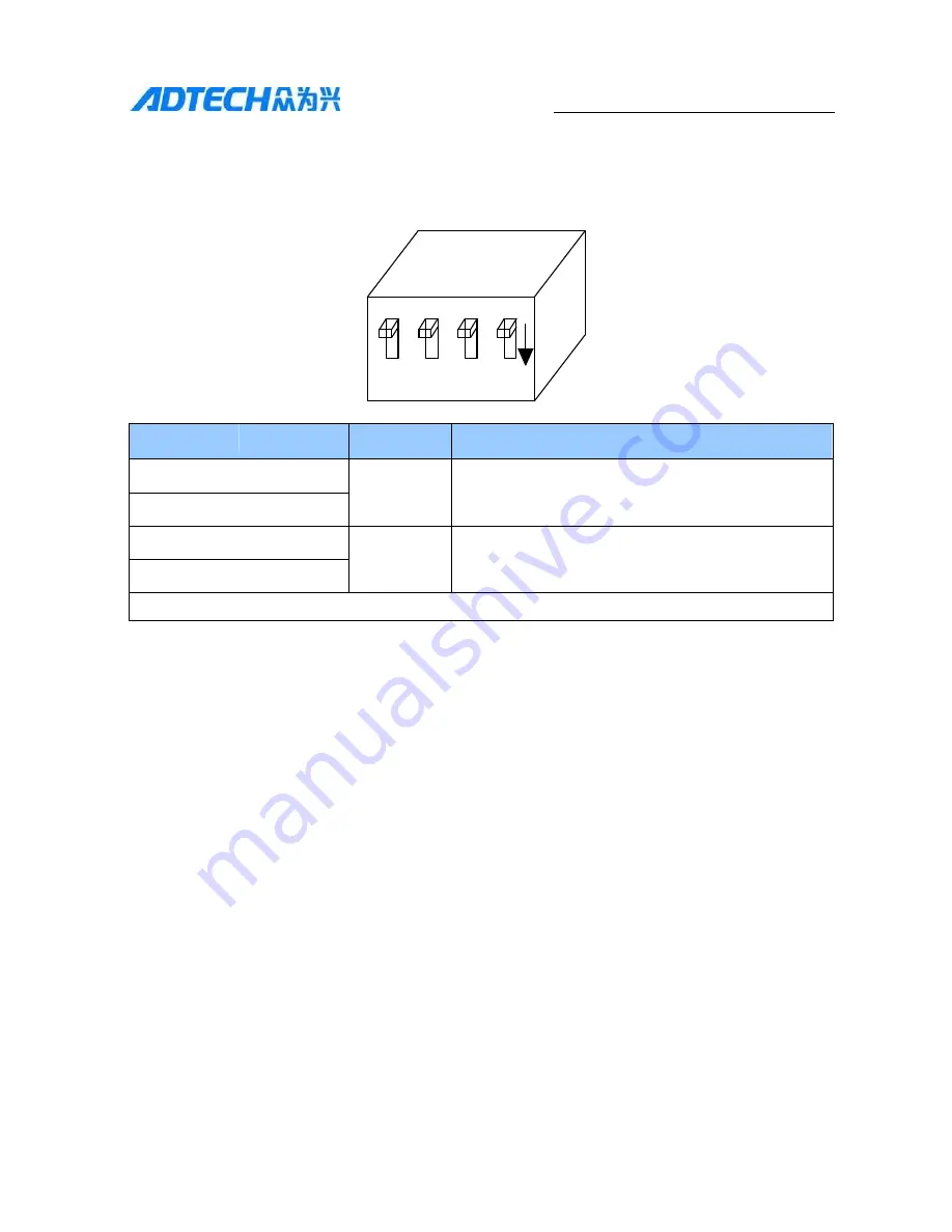
DIP Switch
QS2 series dial switch is as follows:
OF
F
SW1
SW2
SW3
SW4 ON
SW1
SW2
SW3
SW4
00=P+D
100khz
0=RS232
0= 9600bps in default, communication station No.1
01=CCW+CW 100khz
10=A+B
100khz
1=RS485
1=custom, related with the drive internal parameters
11= P+D
500Khz
Note: 0= OFF, 1= ON
Note 1:
Switch1 and 2 are for the selection of pulse mode, Switch 3 is for the selection of
communication mode, and Switch 4 is for the selection of communication baud rate and
communication station number. For details, please refer to Chapter 5.
Note
2:
When the baud rate and communication mode needs changing, the drive shall be
electrified again.
Note 3:
When SW1 SW2=00, only the PLC frequency and the pulse within 100KHZ can be
received; and when SW1 SW2=11, both PLC frequency and the pulse within 500KHZ can be
received.

