� �5!I-��!;fTechnology, Inc.
.. ,
3750 Monroe Avenue
Pittsford, New York 14534-1302
�� (716) 383-8280 • FAX (716) 383-8386
TCX-227 Smart Touch
™
2-Wire
Isolated Temperature Transmitter
Instruction Manual
1.0 INTRODUCTION
These instructions refer to the above model. Supplementary sheets
are attached if the unit has special options or features. For detailed
specifications, see page 4 or refer to the Data Bulletin. All ADTE CH
instruments are factory calibrated and supplied with a label detailing
the calibration. Adjustments are normally not necessary. A simple
check must be performed to verify calibration before installation to
ensure that it matches the field requirement.
2.0 GENERAL DESCRIPTION
The TCX-227 transmitter accepts any of the 11 standard
thermocouple input types and provides a linearized and isolated
output representing temperature. Calibration is extremely easy with
Adtech's
Smart Touch
TM
technology. Simply input your zero value,
touch a button, input your full-scale value and touch another button,
and the unit is calibrated.
The isolated output resolution is 12 bits and provides standard 2-
wire current output signal. Isolation is 600 volts ac or 1000 volts de
from the input to the output/ power supply. Power requirement is
12 to 42 Vdc.
The primary features are:
• Wide range - covers the full usable range of 11 NIST standard
thermocouple types.
• High accuracy, input resolution to 0.3µv.
•
Update rate of 20Hz, -3db response of 5.24 Hz (0.067 msec)
standard.
• RFI resistant.
• No interaction of ZERO and SPAN controls.
• Adtech Smart Touch
™
calibration.
• Small size - DIN mounting package (1 "w x 3.1 "h x 3.6"d).
• Options for NEMA 4 and NEMA 7 housings, SNAP TRAK and
surface mounting.
3.0 INSTALLATION
Electrical Connections
The wire used to connect the instrument to the control system 1/0
should be a twisted pair(s) and sized according to normal practice.
Shielded cable is not normally necessary (if used, the shield must
be grounded at the input negative of the ADTECH instrument and
left floating at the sensor).
Six position compression terminal blocks are provided for 1/0 and
·
power connection. A housing ground terminal is not required due
to non-metallic housing.
-1-
Controls
Instrument controls consist of the following:
• 8 position switch for input configuration and calibration
options.
• Input ZERO and SPAN push buttons (Adtech
Smart
Touch
™
)
• Output ZERO and SPAN pots.
4.0 MAINTENANCE
These instruments are electronic and require no maintenance
except periodic cleaning and calibration verification. If the unit
appears to be mis-operating it should be checked per sections 6.0
and 7.0. MOST problems are traced to field wiring and
I
or
associated circuits. If the problem appears to be with the
instrument, proceed to sections 6.0 and 7.0.
5.0 CONNECTIONS
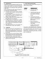
Standard connections are shown below and on the instrument face
plate, Data Bulletin or on attached supplementary sheets.
(+)------
TC Input
(-)----
ADTECH
TOC-227
SPAN@)
OUT CAL
ZERO@
,,
(-) -"""vv.__,
':'P.S.
(+) ..._ ____ _.
(5/ 0) 190-A-000099 Rev. B


